How Bridge Foundations Are Built Underwater: Cofferdams, Caissons and Marine Construction
Building a bridge foundation beneath a river or ocean requires more than pouring concrete in water. Engineers must control hydrostatic pressure, seepage, currents, unstable soils and construction access through carefully designed temporary and permanent works.
Introduction: The Challenge of Building Beneath Water
How can construction workers build a concrete bridge foundation beneath a river without the excavation filling with water? The answer is not one universal technique. Depending on water depth, current, soil conditions, foundation loads and available equipment, engineers may use temporary watertight cofferdams, underwater concrete seals, open or pneumatic caissons, driven piles, drilled shafts, or combinations of these methods.
Underwater bridge foundation construction is a coordinated exercise in structural engineering, geotechnical engineering, hydraulics and marine operations. Water applies hydrostatic pressure to every submerged surface, while currents can move equipment, scour sediment and complicate positioning. Below the riverbed, loose sand, soft clay, gravel or fractured rock may allow seepage or become unstable when excavated. Visibility is often poor, so survey data, instrumentation and carefully controlled procedures replace ordinary visual inspection.
Not every project requires the entire work area to be dry. Some foundations are constructed inside a dewatered cofferdam. Others are built by placing concrete through water, driving piles from a barge, or drilling deep shafts through a temporary casing. The method is selected to provide a stable load path to soil or rock while keeping workers, equipment and materials within safe operating limits.
Key Takeaways
- Cofferdams temporarily exclude water so crews can excavate and construct a footing in a relatively dry workspace.
- Caissons are substantial foundation units or working chambers that can be sunk, excavated through, or assembled afloat and installed underwater.
- Tremie concrete is placed continuously and carefully so cement paste is not washed out by flowing water.
- Piles and drilled shafts transfer bridge loads through shaft resistance, end bearing, or both, often without removing all surrounding water.
- Seepage, uplift, piping, basal heave, scour and temporary-work failure must be addressed before excavation begins.
What Supports a Bridge Beneath the Water?
A typical submerged bridge support consists of a pier, a footing or pile cap, and a deep foundation system. The pier rises above the foundation to carry the superstructure. The footing spreads load over competent soil or rock, while a pile cap connects a group of piles or drilled shafts and distributes forces from the pier.
Driven piles may be made from steel, precast concrete or other specified materials. They are installed by impact or vibratory equipment and develop capacity through end bearing at the pile tip, friction or adhesion along the shaft, or a combination of both. Drilled shafts are formed by excavating a large-diameter hole, stabilizing it with casing or drilling fluid when necessary, placing reinforcement, and filling the shaft with concrete.
Loads include the dead weight of the bridge, traffic, wind, braking, temperature effects, vessel impact where relevant and earthquake forces in applicable regions. Foundations must also resist lateral loads and overturning. The design therefore depends on more than vertical bearing capacity: soil stiffness, scour potential, settlement, group interaction and lateral response are critical.
Cofferdams: Creating a Dry Construction Area Underwater
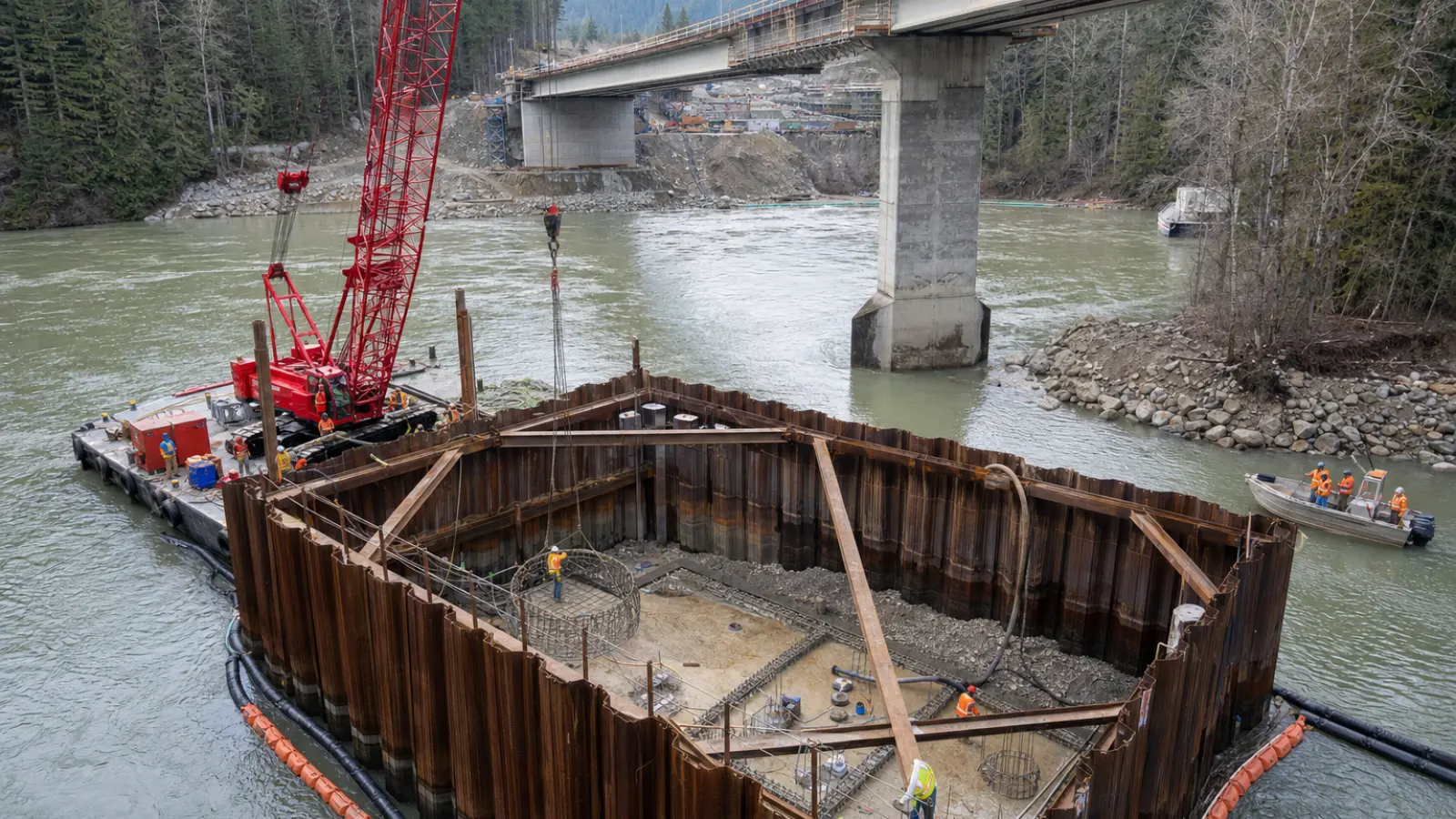
A cofferdam is a temporary enclosure built in or around water to create a controlled excavation. It commonly uses interlocking steel sheet piles driven into the riverbed in a rectangular, circular or cellular arrangement. Once the enclosure is closed, crews excavate inside it, install internal bracing, place a foundation seal if required, and gradually remove water.
The FHWA underwater bridge inspection reference manual describes how cofferdams and underwater concrete foundation seals help engineers create suitable working conditions for bridge foundation construction.
Sheet piles do not simply act as a thin wall against water. The complete temporary works system includes interlocks, walers, struts, corner details, seals and connections to the supporting soil. Internal bracing limits wall movement as excavation proceeds. In some designs, a tremie-placed concrete seal is cast at the base before dewatering. The seal provides a relatively watertight floor and resists upward hydrostatic pressure.
Cofferdams are temporary structures, although portions may remain below the bed or be cut off after construction. They must be designed, installed, inspected and removed or modified with the same discipline applied to permanent works. An apparently simple sheet-pile enclosure can become unstable if the excavation sequence, water levels or brace installation differs from the design assumptions.
Step-by-step cofferdam construction
- Investigate the site. Engineers combine geotechnical borings, laboratory testing, bathymetric surveys and hydraulic studies. The investigation identifies soil layers, bedrock elevation, seepage paths, currents, navigation constraints and scour exposure.
- Install the sheet piles. A template or guide frame helps maintain alignment. Vibratory or impact hammers drive piles to the specified penetration, while crews monitor position, refusal and potential effects on nearby structures.
- Install walers and struts. As excavation advances, horizontal walers distribute wall loads and internal struts or frames restrain the sheets. The sequence is planned so no unsupported height becomes excessive.
- Excavate underwater. Clamshell buckets, long-reach excavators, suction dredges or other equipment remove sediment while the enclosure remains flooded. Survey teams check the excavation level and geometry.
- Place a concrete seal where required. Tremie pipes deliver concrete to the bottom under water. The seal is designed for the expected uplift and seepage conditions and must be placed with controlled continuity.
- Verify the seal and temporary works. Engineers may use concrete records, inspection data, water-level observations, sounding, testing and instrumentation to confirm that the seal and bracing perform as intended.
- Dewater in stages. Pumps lower the internal water level gradually. Water pressure outside the cofferdam remains, so dewatering is stopped or adjusted if wall movement, leakage or uplift becomes unacceptable.
- Construct the permanent foundation. Crews install reinforcement, formwork and the footing or pile cap, then cast the pier connection. Embedded items and construction joints are checked before concrete placement.
- Remove or modify temporary works. The cofferdam may be extracted, cut down, filled, or left in a permitted configuration. Removal must not damage the completed foundation or trigger uncontrolled sediment release.
Why Does Water Not Crush the Cofferdam?
Hydrostatic pressure increases with depth, so the lower portions of a cofferdam generally experience greater water pressure than the upper portions. Pressure acts on both the outside and, before dewatering, the inside. As the interior water level falls, the pressure imbalance increases and creates a demanding load case for the sheet piles and bracing.
Soil pressure adds another load. Excavation removes support from the inside while retained soil pushes toward the enclosure. Depending on drainage conditions, the soil may exert drained or undrained pressure, and water trapped in the soil can contribute additional force. Structural analysis checks sheet-pile bending, interlock behavior, brace compression, connection capacity and overall frame stability.
Geotechnical failure modes are equally important. Water moving beneath or through a cofferdam can cause seepage, piping or internal erosion. Upward water pressure can lift the excavation base or the concrete seal. In soft cohesive soils, removing overburden may cause basal heave. Designers address these risks through adequate embedment, staged excavation, a properly designed seal, relief wells or pumping arrangements where appropriate, and continuous monitoring.
Dewatering before a foundation seal has gained the required strength can be dangerous. The water inside the enclosure may temporarily counteract uplift. Removing it too early can lift, crack or displace the seal and allow sudden inflow or soil movement.
Caisson Foundations: Building Massive Supports Below Water
Caissons are large foundation units or working chambers used to construct foundations below water or below difficult ground. Their defining feature is not simply that they are watertight; they provide a controlled means of sinking, excavating or installing a substantial foundation element.
Open caissons
An open caisson has an open bottom and cutting edge. It is sunk by excavating soil from inside, allowing the unit to descend under its own weight or with controlled assistance. After reaching the design level, the base may be sealed or filled and the upper portion completed as part of the foundation. Open caissons are useful where ground conditions allow controlled excavation and sinking.
Pneumatic caissons
A pneumatic caisson uses compressed air in a working chamber to exclude water and stabilize the excavation at depth. Workers historically entered these chambers through access systems, making pressure control, medical procedures and decompression essential. Modern construction practice treats such work as a highly specialized operation with significant occupational hazards and strict controls.
Floating or box caissons
A floating caisson may be fabricated onshore or in a casting facility, towed into position, sunk and connected to a prepared foundation. This approach can reduce underwater assembly, but it requires accurate marine positioning, sufficient flotation and a seabed capable of accepting the applied loads. It is distinct from a sheet-pile cofferdam because the caisson itself becomes a major foundation component or permanent enclosure rather than merely creating a temporary dry workspace.
How Concrete Is Placed Underwater
Underwater concrete placement usually relies on a tremie system. A tremie is a pipe with its discharge end kept embedded in fresh concrete. Concrete enters through the upper hopper and flows down the pipe, displacing water while the submerged outlet prevents the mix from falling freely through the water column.
Placement must be continuous enough to limit cold joints and carefully controlled to avoid breaking the concrete surface. The pipe is raised only as permitted by the placement procedure, and the discharge remains within the previously placed concrete. Concrete proportions, workability, temperature, reinforcement arrangement and delivery logistics are coordinated before the pour begins.
Anti-washout admixtures may be specified when the exposure, flow conditions or quality requirements justify them. They can improve cohesion, but they do not make careless placement acceptable. Ordinary concrete dumped from a bucket into moving water may segregate, lose cement paste, trap debris and develop weak or contaminated zones. Inspection, test sampling and placement records are therefore important parts of quality assurance.
Pile Foundations and Drilled Shafts
Deep piles and drilled shafts often allow engineers to build a bridge foundation without creating a fully dry excavation. A barge-mounted hammer can drive steel piles through water and sediment into dense soil or rock. Precast concrete piles may be installed where transport, handling and ground conditions permit. Pile installation must account for vibration, noise, nearby structures, refusal, alignment and the possibility of scour exposing unsupported length.
Drilled shafts are constructed by advancing a temporary casing or using a slurry-supported excavation. The casing prevents collapse near the waterline or through unstable strata. Drilling fluid, often a carefully controlled slurry, supports the borehole walls below the groundwater level. After the shaft reaches its design depth, crews clean the base, lower the reinforcing cage and place concrete, commonly using a tremie method so the concrete displaces the slurry without uncontrolled mixing.
Both systems can be connected to a pile cap or pier shaft. Their performance depends on installation quality as well as design calculations. Shaft cleanliness, concrete continuity, reinforcement position and actual ground conditions are monitored because defects may not be visible after completion.
How Engineers Prevent Flooding and Ground Failure
- Dewatering control: Pumps are selected and operated to manage inflow without creating excessive hydraulic gradients outside the enclosure.
- Seepage monitoring: Water levels, turbidity, leakage points and pumping rates can reveal piping or a developing breach.
- Water-pressure instrumentation: Piezometers and other instruments help track pore-water pressure, uplift and changes caused by excavation.
- Scour protection: Rock, articulated blocks, concrete armor or other approved systems may protect the completed foundation and riverbed from erosive flow.
- Emergency planning: Contingency measures can include standby pumps, reserve power, additional bracing, staged backfilling and procedures for rapidly restoring water levels.
Marine construction plans also address changing weather, floods, vessel traffic, tides, wave action and restricted visibility. A cofferdam that is stable during normal flow may face a different load case during a flood or storm, so work limits and evacuation procedures must be defined in advance.
Cofferdams vs. Caissons vs. Deep Piles
| Method | Working principle | Advantages | Limitations | Typical applications |
|---|---|---|---|---|
| Cofferdam | Temporary enclosure excludes water and creates a work area; excavation proceeds inside. | Provides access for conventional footing, reinforcement and formwork; familiar construction sequence. | Requires temporary works, dewatering and control of seepage, uplift and wall movement. | River piers, shallow to moderate water, accessible foundation excavations. |
| Caisson | A large chamber or foundation unit is sunk, excavated through, pressurized or installed afloat. | Can form a substantial foundation at depth and reduce reliance on a broad temporary enclosure. | Specialized marine operations; pneumatic types involve demanding pressure and worker-safety controls. | Deep bridge piers, heavy foundations and difficult submerged sites. |
| Deep piles or drilled shafts | Long or large-diameter elements transfer load through soil resistance, end bearing or both. | Can reach competent strata without fully dewatering the surrounding area. | Installation quality, scour, vibration, drilling stability and underwater inspection require careful control. | Deep water, weak surface soils, high lateral loads and variable riverbeds. |
Construction Equipment Used in Marine Foundations
Marine foundation projects use equipment selected around water depth, access and ground conditions. Floating cranes and spud barges position heavy frames, cages, sheet piles and caisson components. Vibratory and impact hammers install sheet piles and driven piles. Clamshell buckets, dredges and long-reach excavators remove underwater material, while survey boats and real-time positioning systems maintain alignment.
Concrete pumps, delivery barges, tremie pipes and temporary batching arrangements support underwater pours. Divers may inspect components or perform specialized tasks, but engineering teams generally reduce reliance on underwater manual work through prefabrication, instrumentation and remotely operated tools where practical. Every item must be secured against current, wake, wind and sudden changes in water level.
Real-World Engineering Examples
The Brooklyn Bridge and Eads Bridge are documented historical examples of major bridges constructed with pneumatic caisson methods. Their foundations illustrate how engineers used pressurized working chambers to excavate below river level before modern drilling, monitoring and marine equipment were available. These projects also demonstrate that foundation construction can govern the schedule, risk profile and eventual form of an entire bridge.
Modern bridge construction commonly combines methods rather than choosing a single system. A project may use a sheet-pile cofferdam for a near-shore pier, driven piles in one river reach, and large drilled shafts or a floating caisson where water is deeper. The final selection depends on the geotechnical model, hydraulic conditions, vessel access, environmental restrictions, temporary-work risk and the ability to inspect the completed foundation.
Environmental and Construction Safety
Marine construction must control sediment and prevent concrete washout, fuel releases and contaminated water from entering the river or ocean. Turbidity curtains, silt control systems, sealed work areas, treatment of pumped water and careful equipment maintenance may be required by the project’s environmental plan and permits.
Worker safety includes falls into water, vessel movement, lifting operations, confined spaces, electrical equipment near water, diving, compressed-air work and sudden flooding. Cofferdams require documented inspections after installation, after major water-level changes and whenever excavation or bracing progresses. Access ladders, walkways, lighting, rescue equipment and communication systems must remain usable throughout the shift.
Marine traffic and weather create additional hazards. Work zones may need exclusion areas, navigation warnings, coordinated closures and limits on crane operations. Wind, waves, currents and flood forecasts should be incorporated into daily planning rather than treated as unexpected disruptions.
Frequently Asked Questions
How do engineers build bridge pillars in deep water?
They may drive piles or drill shafts from barges, install a caisson, or build a cofferdam around the foundation location. The chosen method depends on depth, currents, seabed conditions, foundation loads and access for marine equipment.
What prevents water from entering a cofferdam?
Interlocking sheet piles, adequate embedment, internal bracing, a low-permeability soil profile and, where needed, an underwater concrete seal limit inflow. Pumps manage residual seepage, but pumping cannot compensate for an inadequately designed enclosure or failed seal.
How is concrete poured underwater?
Concrete is commonly placed through a tremie pipe whose outlet remains embedded in fresh concrete. This controlled discharge displaces water and reduces segregation. The pour is planned for continuity, workability and protection from washout.
What is the difference between a cofferdam and a caisson?
A cofferdam is normally a temporary enclosure that creates a dry or controlled workspace. A caisson is a substantial chamber or foundation unit that is sunk, excavated through, pressurized or installed afloat and may become part of the permanent foundation.
Can bridge foundations be built without dewatering?
Yes. Driven piles, drilled shafts with slurry support, floating caissons and underwater tremie concrete can be used without making the entire work area dry. Dewatering is selected when it improves access, inspection or construction quality and can be performed without unacceptable hydraulic or geotechnical risk.
Conclusion
Underwater bridge foundation construction succeeds when engineers control the interaction between water, soil, temporary works and permanent structural elements. Cofferdams create dry access, caissons provide specialized foundation chambers or units, and piles and drilled shafts transfer loads through difficult submerged ground. Tremie concrete makes reliable underwater placement possible when a dry excavation is impractical.
The most important decisions are made before the first sheet pile is driven: characterize the ground, understand the hydraulic environment, select a buildable load path, design the temporary works and define monitoring and emergency procedures. When structural, geotechnical, hydraulic and marine engineering are coordinated, even deep and turbulent water can become a controlled construction environment.
Sources
- Federal Highway Administration, Underwater Bridge Inspection Reference Manual.