How Elevator Safety Systems Work: Brakes, Overspeed Governors and Fall Protection
Modern elevators use coordinated mechanical, electrical and electronic safeguards to detect abnormal movement, remove driving force and stop the car safely.
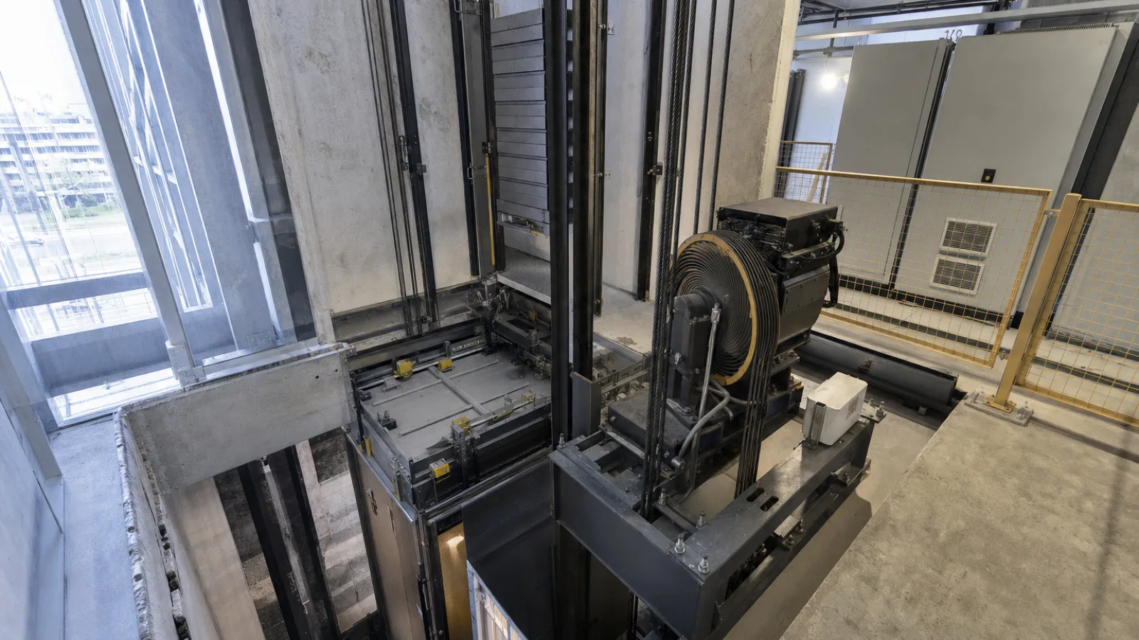
What happens if an elevator suddenly starts falling or moving too fast? The answer is not a single emergency brake. Modern elevator safety systems combine suspension components, machine brakes, overspeed detection, mechanical safety gear, door interlocks, electronic monitoring and pit buffers. Each layer addresses a different failure mode, and several operate independently of the normal drive system.
A car that loses electrical power is not necessarily falling. An elevator moving faster than its rated speed is experiencing overspeed, while uncontrolled movement can occur when the car moves with doors open or without the intended command. Actual free fall is a more extreme condition, and the complete failure of every relevant restraint would be required before it could develop. Safety engineering is designed to make that chain of failures highly unlikely, but equipment still requires correct design, inspection, testing and maintenance.
Key Takeaways
- The machine brake normally holds the elevator when the motor is not driving it, while the safety gear is a separate mechanical stopping device.
- An overspeed governor senses excessive car movement through a governor rope and can initiate both electrical shutdown and mechanical safety-gear engagement.
- Guide rails, suspension systems, counterweights, door interlocks and buffers provide additional protection against different hazards.
- A power failure normally causes the spring-applied machine brake to engage rather than making the car fall.
- Exact arrangements vary among traction, hydraulic, geared, gearless and machine-room-less elevators and must comply with the applicable local code.
How a Traction Elevator Works
In a traction elevator, the car is connected to a counterweight by suspension ropes or, in some installations, coated steel belts. The ropes pass over a traction sheave driven by an electric motor. Grooves in the sheave grip the suspension members sufficiently to transmit motion without requiring the ropes to be rigidly attached to the shaft machinery.
The car and counterweight travel vertically along separate sets of guide rails. The counterweight usually balances the car and a portion of its rated load, reducing the motor torque and energy required for travel. It does not act as a safety brake, however. If a driving component fails, the counterweight can influence the forces and movement of the system, but separate protective devices are still required.
During upward travel, the motor turns the traction sheave so that the car side of the suspension system rises while the counterweight descends. Reversing the motor direction produces downward car travel. A variable-frequency drive or another controller regulates acceleration, leveling and deceleration. At the landing, the controller reduces speed, brings the car to the floor and commands the brake to hold it stationary.
The machine brake is commonly mounted on the motor or traction machine. It does not normally drag on the guide rails. The car's safety gear, by contrast, is mounted on or connected to the car frame and is designed to grip the guide rails if a defined overspeed or related emergency condition occurs.
The Overspeed Governor: How Excessive Speed Is Detected
An overspeed governor is a dedicated speed-sensing device, commonly installed in the hoistway or machine space, with a governor pulley and a separate governor rope linked to the elevator car. As the car moves, the rope circulates over the pulley. If the car exceeds a specified tripping condition, the governor mechanism locks or otherwise restrains the governor rope.
An engineering overview of Otis elevator safety systems explains how controllers, machine brakes, overspeed governors and car safeties provide successive layers of protection.
Centrifugal detection and mechanical triggering
Many governors use centrifugal weights or an equivalent mechanical speed-sensing arrangement. As rotational speed increases, centrifugal force moves the sensing elements outward against calibrated springs or linkages. At the tripping point, the mechanism releases a latch or engages a gripping device. The governor is designed to respond to motion itself, rather than relying only on the elevator controller's software or the building's electrical supply.
Governor operation can initiate an electrical safety action that removes power from the drive and causes the machine brake to apply. If the abnormal movement continues, the governor rope can operate the car safety through a tensioning and linkage arrangement. Some designs also use a governor in the counterweight safety arrangement where required by the equipment design and applicable code. The details differ, but the engineering principle is the same: excessive movement is detected by a dedicated protective path.
Elevator Safety Gear: How the Car Stops on Guide Rails
Safety gear is a mechanical device attached to the car frame, and sometimes to the counterweight in specified configurations. When activated, wedges, clamps, rollers or other gripping elements press against the guide rails. The resulting friction and mechanical resistance convert the car's kinetic energy into heat and deformation while bringing the car to a controlled stop.
Progressive and instantaneous safety gear
Progressive safety gear builds stopping force over a short distance. It is generally used where limiting deceleration is especially important, including many passenger-elevator applications. The gradual engagement helps reduce shock loads on passengers, the car frame, rail brackets and the building structure.
Instantaneous safety gear engages more abruptly. It can be suitable for certain equipment types, speeds and rated conditions, but the permitted arrangement depends on the elevator design and governing requirements. Neither term means that the car stops without forces being transmitted through the structure. The safety gear must be correctly adjusted so that it grips the intended rail surfaces and shares load as designed.
Safety gear is not the same as the machine brake. The machine brake holds the traction machine and normally stops the car during ordinary operation or a power interruption. Safety gear is an emergency device that acts at the car or counterweight and uses the guide rails as the stopping medium. Confusing these functions can lead to incorrect inspection or maintenance decisions.
What Happens During an Elevator Overspeed Emergency?
- Abnormal speed develops: A control fault, drive problem, brake issue or mechanical failure causes the car to move faster than the permitted condition.
- The governor detects the condition: The governor reaches its tripping point and restrains or locks the governor rope.
- The drive is shut down: The electrical safety circuit opens, removing the enable signal or power path to the drive and causing the machine brake to apply.
- The safety gear engages if required: If the car continues moving or the triggering condition demands it, governor-rope movement operates the safety linkage and the gripping elements engage the guide rails.
- The car stops and remains under fault control: The elevator is taken out of normal service. A qualified technician must determine the cause, inspect affected parts and reset or replace components according to the equipment instructions and applicable requirements.
The sequence is not necessarily identical for every elevator. Some systems include dedicated unintended-car-movement protection, dual braking arrangements, electronic speed monitoring or other code-compliant technologies. The important point is that the emergency response does not depend on one software command alone.
Electromechanical Brakes and Power Failure Protection
Most traction elevator machine brakes are fail-safe in their basic principle: springs apply the braking force, while an electrically energized solenoid or brake actuator releases it. When the controller commands movement, the brake coil is energized and the brake opens. When the car stops, a fault occurs or power is lost, the electrical release is removed and the springs apply the brake.
This arrangement explains why a normal power outage does not automatically cause an elevator to fall. The motor stops receiving power and the brake is designed to engage. Depending on the installation, emergency power, battery lowering or rescue equipment may move the car to a landing and open the doors, but these features do not replace the primary mechanical brake or other safety devices.
Brake inspection includes checking lining or friction surfaces, air gaps, springs, pins, release mechanisms, stopping performance and signs of contamination or overheating. A brake that appears to release and apply is not necessarily correctly adjusted. Its holding capacity, redundancy and interaction with the control system must be assessed by qualified personnel.
Elevator Door Interlocks and Safety Circuits
Landing and car doors are among the most important parts of the safety chain. A landing-door interlock mechanically locks the door and provides an electrical confirmation that the lock is engaged. The controller should not permit normal travel unless the relevant doors are closed and locked. A door contact alone is not a substitute for a mechanically effective lock.
Position sensors, leveling sensors, encoder feedback and speed-related signals help the controller determine where the car is and how it is moving. Safety circuits monitor door locks, emergency stops, governor contacts, safety-gear switches, terminal limits and other protective devices. If a circuit opens, the normal response is to remove the run command and apply the brake.
Modern systems may use electronic monitoring and diagnostic networks, but safety-related functions remain subject to prescribed architecture, fault detection and validation requirements. Bypassing a door interlock or shorting a safety circuit is a serious hazard and must never be used as a troubleshooting shortcut.
Buffers, Counterweights and Redundant Protection
Buffers are energy-absorbing devices installed at the bottom of the hoistway, beneath the car and, where applicable, beneath the counterweight. They are intended to limit the consequences of an overtravel event at the bottom of the shaft. Depending on the elevator's speed and design, buffers may use springs, oil or other approved energy-absorbing arrangements.
A buffer is not a normal stopping device and should not be treated as a replacement for the governor, safety gear or machine brake. It is a final protective measure for a specific overtravel condition. The pit must also provide the required clearances and refuge spaces for workers and equipment.
The counterweight balances much of the car mass and rated-load relationship, improving efficiency and reducing motor size. Suspension ropes, terminations, sheaves and belts are selected and maintained with appropriate design margins. Their condition is affected by wear, fatigue, corrosion, alignment, lubrication requirements and repeated bending over sheaves. Safety factors and inspection criteria are defined by the applicable code and equipment design rather than by a single universal value.
Comparison of Major Elevator Safety Devices
| Device | Primary function | Typical trigger | Where it acts |
|---|---|---|---|
| Machine brake | Stops and holds the traction machine during normal stops, faults and power loss | Controller command, safety-circuit opening or loss of electrical release | Motor or traction machine |
| Overspeed governor | Detects excessive car or governor-rope speed and initiates protective action | Mechanical speed threshold | Governor pulley, rope and related trip mechanism |
| Safety gear | Stops the car or counterweight by gripping the guide rails | Governor activation or another approved triggering arrangement | Guide rails beside the car or counterweight |
| Buffers | Absorbs energy during defined bottom-overtravel conditions | Physical contact at the pit end of travel | Hoistway pit |
Engineering Calculations Behind Elevator Safety
The basic energy relationship is useful for understanding why stopping distance and deceleration matter. The kinetic energy of a moving mass can be represented by E = 1/2mv², where m is mass and v is velocity. Because velocity is squared, a modest increase in speed can produce a disproportionately larger increase in energy that must be dissipated.
Simplified illustrative example
Assume, for illustration only, that a moving elevator mass is 1,500 kg and its speed is 2 m/s. Its kinetic energy would be approximately 3,000 joules before considering gravity, rope dynamics, counterweight effects, friction, brake characteristics or the changing load condition. If an idealized stopping distance were 0.5 m, the average energy-related stopping force would be roughly 6,000 N, again excluding those real-world effects.
This is not a certified elevator design calculation or a prediction of actual stopping performance. Real analysis must consider car and passenger mass, counterweight balance, governor trip behavior, rail friction, guide-rail stiffness, safety-gear geometry, deceleration limits, suspension elasticity, stopping distance and code requirements. Engineers also evaluate worst-case loading and fault combinations rather than relying on a simple textbook model.
Elevator Safety Standards
EN 81-20 establishes safety rules for the construction and installation of electric and hydraulic lifts in its intended scope, while EN 81-50 addresses design rules, calculations, examinations and tests of lift components. In North America, ASME A17.1/CSA B44 provides the principal safety code framework for elevators and related equipment.
The applicable requirement depends on jurisdiction, equipment type, installation date, building use, modernization scope and the edition adopted by the authority having jurisdiction. Standards should therefore be obtained from the responsible standards organization or applied through the project engineer, code authority and qualified elevator contractor. A general description of a safety device cannot replace a code review for a specific installation.
Inspection, Testing and Preventive Maintenance
Elevator safety systems are only effective when their components remain correctly adjusted and free from damage. A maintenance and inspection program commonly addresses:
- Governor: Check the pulley, rope, tensioning arrangement, seals, trip mechanism and electrical contacts; perform required operational tests.
- Safety gear: Inspect linkages, wedges or rollers, clearances and guide-rail condition, then conduct authorized tests and reset procedures.
- Machine brake: Examine friction surfaces, springs, release components, alignment, air gap and holding or stopping behavior.
- Door interlocks: Verify mechanical locking, electrical contacts, clutch operation, door-reopening devices and proper leveling relationships.
- Buffers and pit equipment: Check condition, mounting, leakage where relevant, clearances, switches, lighting and safe access conditions.
Testing must be performed by qualified elevator personnel using the manufacturer's procedures and the applicable inspection regime. A safety trip can damage components or leave the elevator in an unsafe condition if it is reset incorrectly. Records of tests, defects, repairs and out-of-service conditions are important for building owners, facility managers and regulators.
Future Elevator Safety Technology
Connected elevators increasingly use sensors to monitor vibration, motor current, brake behavior, door cycles, temperature, leveling accuracy and drive faults. Condition-monitoring systems can help identify a developing problem before it becomes a service interruption or a safety-critical defect.
Predictive maintenance is most useful when it supports, rather than replaces, physical inspection and legally required testing. Data quality, cybersecurity, access control and clear responsibility for alarm response are essential. A sensor that reports a fault is not itself a mechanical safeguard, and a cloud connection should not be treated as a substitute for an independent governor, brake or safety circuit.
Frequently Asked Questions
Can an elevator fall if its cable breaks?
A traction elevator typically has multiple suspension ropes or belts, and its governor and safety gear are designed to address excessive car movement. A single suspension-member failure does not automatically mean free fall. The exact response depends on the elevator's design, condition and applicable requirements, so the system should never be treated as immune to all failures.
What happens when an elevator loses power?
The drive stops and the spring-applied machine brake normally engages. The car may remain between floors until normal or emergency rescue procedures are carried out. Some installations use standby power or automatic rescue devices to move the car to a landing, but passengers should not force doors or attempt self-rescue.
How does an overspeed governor work?
A governor pulley rotates with a rope connected to the car. A centrifugal or equivalent mechanical mechanism detects excessive speed, then trips a switch and may restrain the governor rope. That action can shut down the drive and activate the car's mechanical safety gear.
Do elevator brakes work without electricity?
Many traction machine brakes are spring-applied and electrically released. Consequently, loss of electrical power removes the release force and applies the brake. Specific brake arrangements vary, so maintenance personnel must follow the equipment documentation and applicable code.
What stops an elevator from falling down the shaft?
Protection is layered: the suspension system supports the car, the machine brake holds the traction machine, the governor detects overspeed, the safety gear grips the guide rails, and buffers absorb energy during defined bottom-overtravel events. Door interlocks and safety circuits also prevent hazardous operation under abnormal conditions.
Conclusion
Elevator safety systems work as a coordinated mechatronic chain rather than as one emergency brake. The controller manages normal motion, the machine brake removes driving movement and holds the car, the governor provides independent overspeed detection, and the safety gear can stop the car on its guide rails. Door interlocks, suspension components, counterweights, buffers and inspection procedures add further layers.
For engineers and building professionals, the practical lesson is to evaluate the complete system: mechanical energy, electrical fault paths, sensor behavior, clearances, maintenance access and code compliance. Elevators are carefully engineered machines, but their safety depends on correct installation, commissioning, testing and ongoing work by qualified specialists.
Sources
Applicable editions of EN 81-20, Safety rules for the construction and installation of lifts; EN 81-50, Design rules, calculations, examinations and tests of lift components; and ASME A17.1/CSA B44, Safety Code for Elevators and Escalators. Requirements vary by jurisdiction and adopted edition.
How to verify these figures yourself
For a project-specific review, confirm the rated speed, car and counterweight masses, stopping distances, brake data, governor settings and safety-gear test results in the elevator manufacturer's documentation and inspection records. Then compare them with the code edition adopted by the authority having jurisdiction. The illustrative energy and force values in this article are educational examples, not certified design values.