Electrohydraulic Actuators in Construction Machinery: Sensors, Control Loops, Efficiency, and Failure Diagnosis
Electrohydraulic actuators combine hydraulic power with electronic sensing and control. This practical guide explains system architecture, calibration, efficiency, and fault diagnosis.
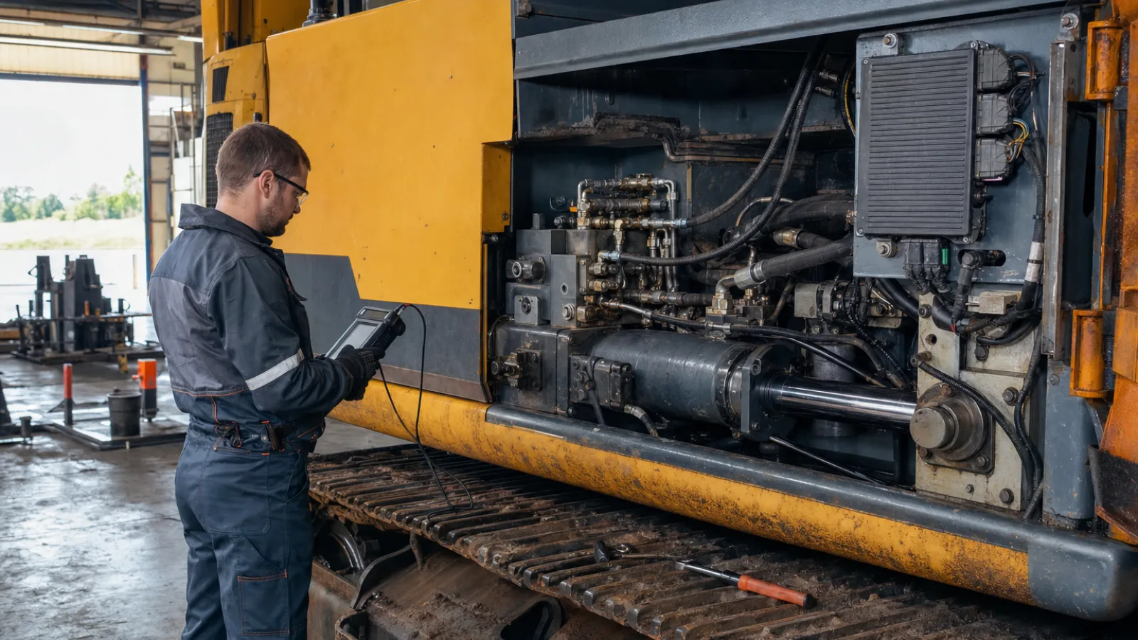
Electrohydraulic actuators combine hydraulic power with electronic sensing and control to move excavator booms, loader arms, crane mechanisms, aerial-platform components, compact-equipment attachments, and other construction-machine functions. The hydraulic circuit supplies high force; electronics determine how quickly, how far, and under what conditions that force is applied.
This combination is useful when a machine must deliver controlled motion under changing loads. A modern system may use a proportional valve, cylinder or hydraulic motor, position and pressure sensors, and a controller connected to the machine network. Technical references such as Moog’s electrohydraulic actuator technology illustrate the broader engineering principle: electronic commands can regulate hydraulic power precisely when the valve, feedback devices, software, and mechanical load are treated as one system.
Key takeaways
- An electrohydraulic actuator is not just a cylinder with a wire; it is part of a complete power, sensing, control, and mechanical chain.
- Closed-loop control compares commanded movement with measured feedback and corrects the valve command as conditions change.
- Jerky motion, drift, heat, and intermittent faults can originate in hydraulics, electronics, sensors, software, or mechanical linkage.
- Measured data, calibration records, contamination control, and safe isolation are more reliable than replacing parts by guesswork.
What are electrohydraulic actuators?
An electrohydraulic actuator converts an electrical command into controlled hydraulic motion. The command may originate from a joystick, machine controller, automation system, grade-control function, or attachment-control module. The controller sends a signal to a proportional or servo valve, which meters hydraulic flow and sometimes pressure to a hydraulic cylinder or hydraulic motor.
A conventional hydraulic actuator can operate with a manually operated valve, a mechanically linked control, or a relatively simple open-loop electrical command. An electrohydraulic actuator system adds electronic computation and feedback. Sensors measure variables such as position, pressure, temperature, flow, angle, or load, allowing the controller to determine whether the physical response matches the requested motion.
The actuator is therefore only one part of a larger system. Reliable performance depends on hydraulic power generation, fluid conditioning, valve response, sensing, control logic, communications, mechanical geometry, and the external load. A fault in any one of these areas can appear as an actuator problem.
How an electrohydraulic actuator system is built
Hydraulic power unit
The power unit normally includes an engine-driven or electric-motor-driven pump, reservoir, filtration, relief protection, and the associated hoses and manifolds. Some circuits also use an accumulator, load-sensing control, or pressure-compensated pump. The power unit must provide sufficient flow and pressure without excessive restriction, aeration, contamination, or heat generation.
Proportional or servo valve
A proportional valve changes spool position in response to an electrical command, varying the effective flow path. A servo valve can provide more precise and faster response in applications designed for that level of control, but not every construction machine uses one. Valve neutral position, deadband, hysteresis, contamination sensitivity, and pressure drop all affect motion quality.
Hydraulic cylinder or hydraulic motor
Hydraulic cylinders produce linear force and travel. Hydraulic motors produce rotary torque and speed. Cylinder bore, rod area, stroke, seals, bearings, and mounting geometry influence force, speed, friction, and stability. A motor-driven function also depends on displacement, case drainage, and the load’s inertia.
Sensors
Position sensors can measure cylinder stroke, spool position, shaft angle, or linkage angle. Pressure sensors reveal supply, port, load, or pilot pressure. Flow, oil-temperature, load, inertial, and angle sensors may be added where the machine requires better coordination or protection. Sensor range, polarity, resolution, mounting, wiring, and signal plausibility are as important as the sensor’s nominal accuracy.
Electronic controller and communications
The controller interprets the operator or automation command, compares it with feedback, applies limits and control rules, and sends a valve command. It may exchange data over a Controller Area Network (CAN) bus or another machine-control network. Fault handling can limit motion, place a valve in neutral, trigger an alarm, or request a controlled shutdown.
Mechanical linkage and load
Linkage geometry changes the force and speed relationship through the stroke. Friction, backlash, bent components, misalignment, external loads, and structural compliance can make a healthy hydraulic circuit appear poorly tuned. The controller cannot compensate indefinitely for a seized bearing, damaged cylinder rod, or unexpected load path.
| Component | Primary function | Typical diagnostic clue |
|---|---|---|
| Pump and hydraulic circuit | Provide conditioned fluid at the required pressure and flow | Low pressure, heat, noise, or slow movement across several functions |
| Proportional or servo valve | Meter flow and direct actuator movement | Deadband, sticking, uneven response, or one-direction weakness |
| Actuator and linkage | Convert fluid power into machine motion | Drift, binding, unequal speed, leakage, or mechanical play |
| Sensors and wiring | Measure position, pressure, temperature, or load | Implausible feedback, intermittent readings, or endpoint errors |
| Controller and network | Calculate commands, limits, and fault responses | Communication faults, missing commands, or incorrect parameter behavior |
How the control loop produces accurate machine movement
In a closed-loop hydraulic control system, the requested position, speed, or force is the setpoint. A sensor reports the actual condition. The controller calculates the error between the setpoint and feedback, then adjusts the valve command. Hydraulic flow changes the actuator motion, and the sensor reports the new result. This cycle repeats continuously.
| Control arrangement | How it works | Typical limitation |
|---|---|---|
| Open loop | A command is sent without continuously checking the resulting position or force | Performance changes with load, friction, temperature, and supply conditions |
| Closed loop | Measured feedback is compared with the command and used for correction | Requires reliable sensors, tuning, wiring, and fault handling |
Proportional control increases or decreases the corrective command according to the error. Integral action can reduce persistent error, while derivative action can anticipate changing error and help control dynamic response. These functions are commonly associated with proportional-integral-derivative (PID) control, but not every machine uses a full PID algorithm. Some systems use maps, feed-forward terms, pressure compensation, state logic, or model-based controls.
Important response characteristics include deadband, hysteresis, delay, overshoot, oscillation, and settling time. A valve with a large neutral deadband may produce delayed starts. Excessive gain may cause hunting or oscillation. Integral action can create overshoot if the actuator is limited or mechanically blocked. Load changes can alter the response even when the electrical command is unchanged.
Calibration and tuning must match the specific valve, sensor, cylinder, linkage, controller, and operating conditions. A parameter set that works on one machine should not be treated as universal. Temperature, oil viscosity, attachment mass, supply pressure, and mechanical wear can all change the response.
Why construction machinery uses electrohydraulic actuators
Electrohydraulic actuators offer several practical advantages in construction machinery:
- Precise movement: Feedback and controlled valve response can improve positioning, smooth starts and stops, and repeatability.
- Function coordination: The controller can coordinate boom, arm, bucket, travel, steering, stabilizer, or attachment functions rather than treating every valve as an isolated control.
- Operator control: Motion maps and limits can adapt response to the selected work mode or attachment.
- Potential efficiency gains: Demand-based flow, coordinated pump and valve control, reduced throttling, and fewer corrective movements can reduce wasted energy in suitable applications. Actual results depend on the hydraulic architecture and duty cycle.
- Usable diagnostic data: Command, feedback, pressure, temperature, current, and fault history can support service planning and condition monitoring.
- Automation integration: Electronic actuation can interface with grade control, attachment recognition, machine protection, semi-automated cycles, and safety functions.
The trade-off is greater system complexity. Wiring faults, sensor drift, software parameters, network interruptions, and controller power quality become relevant failure modes. Hydraulic contamination can damage precision valve components, while poor grounding or moisture ingress can produce intermittent electronic symptoms. Qualified diagnostics are essential because a fault code or unusual movement does not identify a failed component by itself.
Commissioning and calibration checklist
Commissioning should follow the machine manufacturer’s service documentation and the site’s lockout/tagout procedures. Hydraulic pressure can remain dangerous after a pump stops, so pressure-release and isolation requirements must be followed before inspection or service.
- Confirm the specified hydraulic fluid, oil level, filtration condition, hose routing, electrical supply, grounding, and connector security.
- Inspect for air, external leaks, contamination, damaged seals, bent rods, misalignment, loose mounts, and mechanical binding.
- Verify sensor installation, range, polarity, scaling, connector pinout, and plausibility against the service display or a known reference.
- Check valve neutral position, command direction, enable conditions, and response without bypassing protective interlocks.
- Remove air and warm the system according to the manufacturer’s procedure. Do not assume that a generic warm-up time or bleeding method is suitable.
- Establish zero and end-stop references only in a safe, controlled condition with the attachment or structure properly supported.
- Test unloaded movement progressively, then test under representative load while observing limits and safe operating zones.
- Record baseline pressure, command, position, response time, temperature, supply voltage, and fault-code data.
- Confirm that emergency stops, interlocks, overload protection, travel limits, and restricted-motion functions operate correctly.
Calibration values and test pressures must come from the machine’s service documentation, not generic internet guidance. If a calibration procedure requires movement near a suspended load, pinch point, or unstable attachment, use the manufacturer’s prescribed controls and competent personnel.
Diagnosing common electrohydraulic actuator failures
Begin with safe isolation, visual inspection, and the machine’s documented diagnostic procedure. Never disconnect hydraulic lines or loosen fittings on a pressurized circuit.
| Symptom | Likely causes across the system | First checks |
|---|---|---|
| Actuator does not move | No enable signal, low supply voltage, open circuit, blocked valve, low hydraulic pressure, seized linkage, or controller inhibit | Check safety conditions, power and grounds, command data, pressure, valve current, and mechanical freedom |
| Slow or weak movement | Restricted filter, low pump output, relief setting issue, internal cylinder leakage, incorrect valve command, sensor limiting, or excessive load | Compare pressure and flow with the service specification; check command, temperature, leakage, and load conditions |
| Jerky motion or oscillation | Air, contamination, sticky spool, sensor noise, poor tuning, mechanical binding, loose linkage, or unstable feedback | Inspect oil and connections, trend feedback, observe valve command, and separate unloaded from loaded behavior |
| Position drift or failure to hold | Internal cylinder leakage, valve leakage, load-induced movement, faulty position sensor, incorrect zero, or control logic | Compare commanded position with actual feedback and isolate hydraulic holding ability from sensor indication |
| Excessive heat | Continuous relief flow, throttling, pump-control fault, restricted return, incorrect fluid, high leakage, or excessive duty cycle | Review pressure-versus-command behavior, filter and cooler condition, fluid level, and temperature trend |
| Unexpected noise or vibration | Cavitation, aeration, low reservoir level, pump wear, loose mounting, resonance, or rapid valve switching | Check fluid level and suction integrity, listen for changes with load, and inspect mounting and pressure stability |
| Intermittent operation or communication faults | Moisture, corroded terminals, broken conductors, poor ground, voltage drop, CAN wiring fault, or controller reset | Inspect harness movement points, supply voltage under load, connector retention, network status, and event timing |
| Wrong direction or incorrect endpoint | Reversed polarity, incorrect scaling, swapped ports, wrong parameter set, sensor orientation error, or linkage installation error | Verify command direction, sensor polarity, port identification, calibration values, and physical geometry |
A diagnostic code identifies a detected condition, signal range, communication problem, or protective response. It does not automatically prove that the associated sensor, valve, or controller is defective. Confirm the circuit and the physical response before replacing parts.
Using diagnostic data instead of guesswork
The most useful diagnostic comparison is often between command and response. Capture the requested command, valve current or duty signal, sensor feedback, pressure, flow where available, oil temperature, supply voltage, and timing. Record behavior during startup, steady movement, reversal, load changes, and the moment a fault occurs.
- A command is present but valve current or pressure does not respond: investigate the valve driver, wiring, valve, pump supply, and hydraulic restriction.
- Pressure and valve response are normal but position feedback is implausible: investigate the position sensor, scaling, mounting, connector, and linkage.
- Feedback changes while the actuator does not move: investigate sensor mounting, mechanical decoupling, valve flow, blocked passages, and binding.
- Movement is correct unloaded but poor under load: investigate pressure capacity, load-sensing behavior, leakage, structural friction, and control tuning.
- The symptom appears with harness movement or temperature change: prioritize connectors, grounds, conductor breaks, and voltage-drop testing.
Appropriate tools may include a multimeter, pressure gauges, flow-testing equipment, a scan tool, and a data logger. An oscilloscope can reveal sensor noise, PWM command irregularities, voltage drop, or communication disturbances where the machine documentation supports that test. Use test points and pressure limits specified by the manufacturer.
A practical logic sequence is: verify safety and basic conditions; reproduce the symptom; isolate electrical command from hydraulic response; compare feedback with a known reference; inspect the mechanical load path; repair the confirmed cause; then repeat the test and update the baseline record.
Maintenance practices that protect actuator performance
Fluid cleanliness is central to electrohydraulic reliability. Use the specified fluid, protect open ports during service, maintain filtration, and investigate contamination rather than simply replacing a filter. Filter inspection and replacement intervals should follow manufacturer guidance and be adjusted for duty cycle and working environment.
Routine maintenance should include:
- Checking leaks, cylinder seals, rod surfaces, bearings, mounts, and alignment.
- Inspecting harnesses, connectors, grounds, shielding, and moisture protection at vibration and flex points.
- Confirming that sensor brackets, targets, linkages, and mechanical reference points have not moved.
- Reviewing software versions, parameters, calibration files, and access controls before changes are made.
- Trending temperature, response time, drift, pressure behavior, and repeated fault codes against a known baseline.
- Maintaining clear service records that identify the test condition, measured value, repair, and post-repair result.
Replacing a valve or controller before checking contamination, wiring, supply voltage, grounding, and mechanical binding can create a repeat failure. A new component may be exposed to the same root cause, or a parameter mismatch may introduce a different symptom.
Choosing or upgrading an electrohydraulic actuator system
Selection begins with the load profile, not the actuator nameplate alone. Define required force or torque, stroke or rotation, speed, duty cycle, load reversals, environmental exposure, and available pressure and flow. Then specify the required accuracy, repeatability, response time, holding behavior, and fail-safe state.
Review sensor resolution and redundancy, valve flow capacity, pressure rating, leakage characteristics, controller compatibility, communications protocol, diagnostics, and the machine’s existing pump and electrical architecture. Connected equipment also requires appropriate access control, software-change management, and cybersecurity consideration for the control network.
Serviceability matters as much as peak performance. Confirm spare-parts availability, calibration support, test connections, technical documentation, technician capability, and total lifecycle cost. An upgrade that requires major changes to pump control, wiring, software, mechanical mounting, or safety validation may be unsuitable even if the actuator itself meets the force requirement.
Focused FAQ
What is an electrohydraulic actuator?
It is a hydraulic cylinder or motor controlled through an electronic command, usually with feedback from position, pressure, or other sensors. The complete system includes the pump, valve, controller, wiring, and mechanical load.
How is it different from a conventional hydraulic actuator?
A conventional arrangement may rely on manual, mechanical, or open-loop valve control. An electrohydraulic system uses electronic logic and may compare measured movement or pressure with the requested result for automatic correction.
What sensor faults commonly affect actuator motion?
Open or short circuits, incorrect scaling, reversed polarity, sensor drift, mechanical displacement, noisy signals, and poor connector contact can cause incorrect speed, endpoint, direction, or holding behavior.
Can an electrohydraulic actuator save energy?
It can, when coordinated pump and valve control supplies only the required flow and reduces throttling or unnecessary corrective movement. Savings are application-dependent and should be confirmed from measured duty-cycle data.
How often should it be calibrated?
Use the machine manufacturer’s interval and recalibrate after component replacement, linkage work, sensor displacement, software or parameter changes, or symptoms such as drift and incorrect endpoints.
What should be checked first when movement becomes jerky?
Check safety conditions, oil level and aeration, contamination, connectors, sensor feedback, valve command, mechanical binding, and temperature. Do not assume the valve is at fault until command and response data support that conclusion.
Conclusion
Reliable electrohydraulic actuators depend on the interaction of hydraulics, electronics, sensors, software, and mechanics. Accurate motion is not created by a controller alone: the fluid must be clean, the valve must respond, feedback must be credible, the linkage must move freely, and the control parameters must suit the machine.
For construction-equipment engineers, fleet managers, and technicians, the most effective approach is disciplined measurement. Follow safe isolation procedures, compare command with feedback, record pressure and temperature behavior, preserve calibration data, and use preventive maintenance to identify trends before a failure stops the machine.
Sources
- ISO 4413, Hydraulic fluid power — General rules and safety requirements for systems and their components.
- ISO 12100, Safety of machinery — General principles for design — Risk assessment and risk reduction.
- ISO 13849-1, Safety of machinery — Safety-related parts of control systems — Part 1: General principles for design.
- SAE J1939 series, Serial Control and Communications Heavy Duty Vehicle Network.