Long-Span Cantilever Balcony Structural Design: 3–5 m Guide
Designing a 3–5 metre balcony without exterior columns requires more than selecting a thicker slab. This engineering guide explains load paths, Eurocode 2 calculations, reinforcement anchorage, connection design, deflection control, analysis software, detailing, and practical structural alternatives.
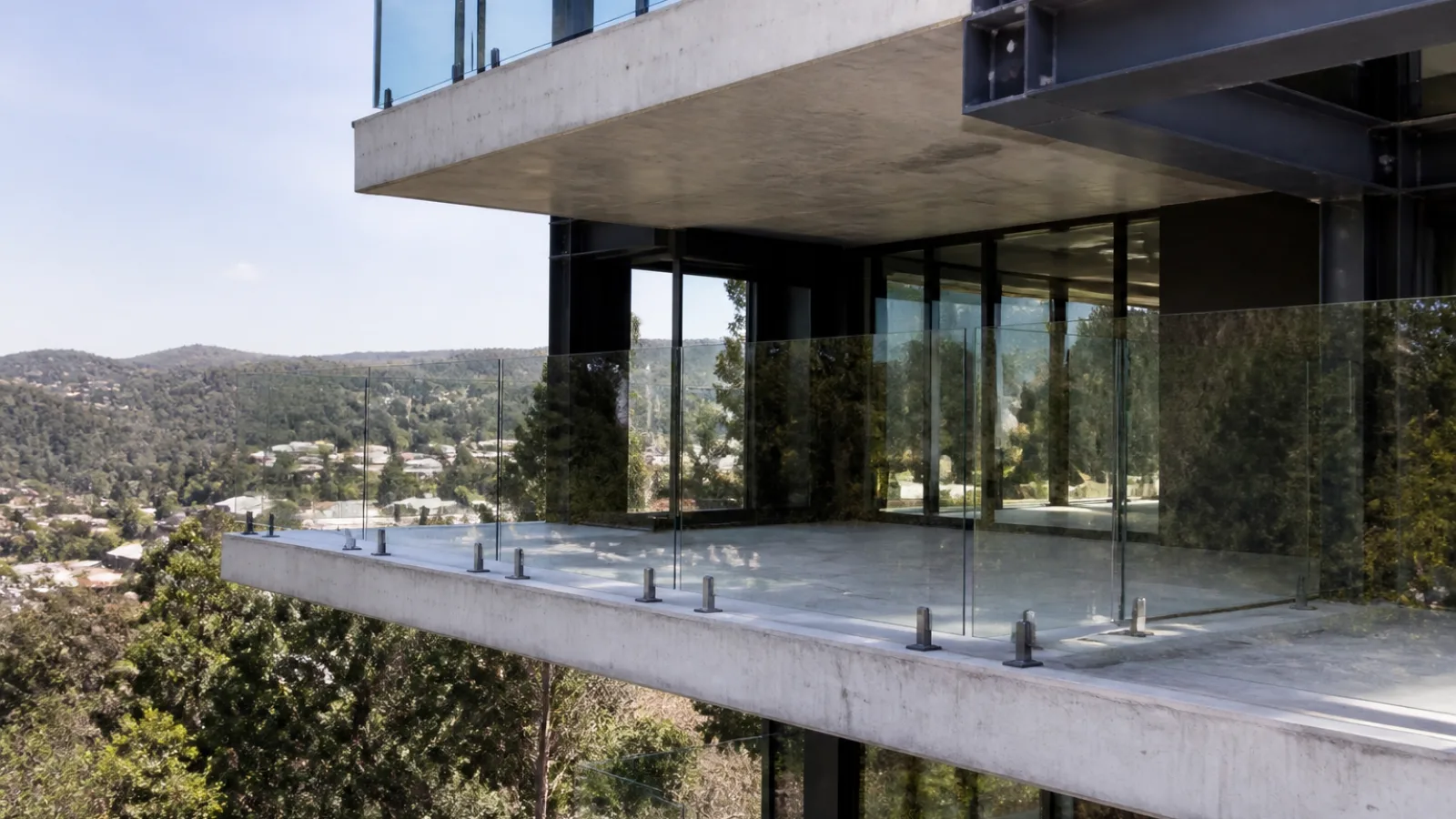
A 3–5 metre balcony projecting beyond a façade can be built without exterior columns, but it is a demanding structural engineering problem. The balcony must transfer gravity loads, wind actions, torsion, bending moments and serviceability effects back into the building through a reliable moment-resisting connection.
In long-span cantilever balcony structural design, the outer edge is free and the building-side support provides the resistance. The most highly stressed reinforcement is therefore normally at the top of a reinforced concrete cantilever near the support—not at the lower surface near the free edge. The final arrangement must be designed and approved by a qualified structural engineer under the governing building regulations and National Annex.
This article provides an educational calculation framework. It is not a construction specification, and the numerical example cannot establish the safety of a real building without project-specific analysis, drawings, material certificates, ground and foundation checks, fire design, durability assessment and site verification.
1. Structural Behaviour of Long Cantilever Balconies
A cantilever projection is the distance measured perpendicular to the façade from the structural support to the free edge. It must not be confused with the balcony width parallel to the façade. A balcony may be 4 m deep and 6 m wide; the critical gravity calculation is generally performed over the 4 m projection, while the 6 m width affects load distribution, edge beams, torsion and the building frame.
For a uniformly loaded cantilever, the idealised support actions are:
Support moment: MEd = wEdL²/2
Support shear: VEd = wEdL
These relationships show why projection length is so important. Doubling the projection quadruples the bending moment and doubles the shear. A 4 m balcony is not simply a larger version of a 2 m balcony.
- Negative bending: gravity loading produces tension at the top near the support.
- Shear: the highest vertical shear occurs at the building connection.
- Torsion: eccentric parapets, edge beams, concentrated furniture and uneven occupancy can twist the balcony and its support.
- Deflection: cantilevers are especially sensitive to stiffness, cracking, creep and shrinkage.
- Cracking: cracks can form at the support, around openings, at thermal breaks and where reinforcement is interrupted.
- Thermal movement: an exposed balcony undergoes temperature changes that can stress finishes and connectors.
- Vibration: rhythmic walking, gatherings and lightweight finishes may produce uncomfortable movement even when strength is adequate.
The building-side connection is therefore part of the balcony structure. A slab that appears fixed in a simple calculation is not genuinely fixed unless the supporting beam, wall, columns, reinforcement and foundations can provide the required rotational stiffness and resistance.
2. Structural Systems and Possible Solutions
Conventional reinforced concrete slab
A thick, heavily reinforced slab can be suitable for shorter projections, particularly where it is monolithic with a deep internal beam or wall. At 4–5 m, slab self-weight becomes a major load and long-term deflection can make a conventional flat slab inefficient or impractical.
Reinforced concrete cantilever beams
One or more deep beams running perpendicular to the façade can support a thinner balcony slab. This concentrates the main bending resistance into beams and provides a clearer load path. Beam depth, internal support stiffness, torsion and architectural coordination must be checked.
Steel cantilever beams
Steel UB, I-section, box or fabricated plate girders can achieve long projections with lower self-weight than reinforced concrete. They require robust moment connections, corrosion protection, fire design, vibration checks and careful waterproofing. Steel beams may be concealed within the floor zone or expressed below the balcony.
Post-tensioned concrete
Post-tensioning can improve span efficiency and control tensile cracking and deflection. It requires specialist design, tendon profiling, anchorage-zone reinforcement, stressing access, fire and durability design, and strict coordination with openings and services.
Composite or concealed transfer systems
Steel-concrete composite balconies, concealed transfer members and continuous moment-resisting frames can provide practical solutions where the architectural brief prohibits visible columns. Their feasibility depends on the existing or proposed building grid, erection sequence and connection access.
A conventional slab may become unsuitable when its required thickness increases self-weight faster than it increases useful capacity, when long-term deflection exceeds acceptable limits, or when the support cannot develop the necessary moment. Alternative systems should be compared at concept stage rather than after architectural design is complete.
3. Worked 4 m Cantilever Balcony Calculation
The following is an illustrative one-metre-wide strip calculation for a 4 m projection and a 6 m balcony width. It uses Eurocode principles and indicative values only. The applicable National Annex, occupancy category, wind actions, parapet actions, fire requirements and project-specific load combinations must be confirmed by the engineer.
| Parameter | Illustrative value |
|---|---|
| Projection | 4.00 m |
| Width parallel to façade | 6.00 m |
| Outer support | None |
| Structural support | Moment-resisting connection to primary structure |
| Concrete | C30/37 |
| Reinforcement | B500B |
| Initial slab thickness | 300 mm for illustration |
| Design basis | EN 1990, EN 1991 and EN 1992 with National Annex |
3.1 Permanent and imposed loads
Assume a 300 mm slab, 25 kN/m³ concrete density, 1.50 kN/m² finishes and screed, and 0.30 kN/m² waterproofing and ceiling allowance:
Slab self-weight = 0.30 × 25 = 7.50 kN/m²
Permanent area load Gk = 7.50 + 1.50 + 0.30 = 9.30 kN/m²
For illustration, adopt a balcony imposed load Qk = 4.00 kN/m². This value is not universal; the occupancy category and National Annex may require another value. A 0.75 kN/m parapet line load is also assumed at the free edge.
3.2 Ultimate and serviceability combinations
Using a basic persistent design combination:
qEd = 1.35Gk + 1.50Qk
qEd = 1.35(9.30) + 1.50(4.00) = 18.56 kN/m²
The factored parapet line load is approximately 1.35 × 0.75 = 1.01 kN/m, subject to the governing code and action classification.
The characteristic service load for a simple sustained-plus-variable check is:
qser = 9.30 + 4.00 = 13.30 kN/m²
3.3 Bending moment and shear
For a one-metre strip with L = 4.00 m:
MEd = qEdL²/2 + PEdL
MEd = 18.56 × 4²/2 + 1.01 × 4 = 152.5 kNm/m
VEd = qEdL + PEd = 18.56 × 4 + 1.01 = 75.3 kN/m
The parapet term has a relatively small effect in this example, but concentrated planters, masonry screens, glazing systems or balustrade posts may produce substantially larger local actions.
3.4 Preliminary flexural reinforcement
Assume effective depth d = 255 mm after allowing for cover and bar diameter. For a preliminary lever arm z = 0.90d = 230 mm and fyd = 500/1.15 = 435 MPa:
As,req = MEd/(z fyd)
As,req = 152.5 × 10⁶/(230 × 435) = 1,524 mm²/m
An illustrative arrangement of 16 mm bars at 125 mm centres provides approximately 1,608 mm²/m. This is only a preliminary flexural selection. It must be checked for minimum reinforcement, spacing, anchorage, crack width, construction tolerances, curtailment, transverse distribution and the actual analysis envelope. Main bars should normally run perpendicular to the façade and be placed at the top over the support.
3.5 Shear resistance
For a 300 mm slab, the design shear stress is approximately:
vEd = VEd/(bwd) = 75,300/(1,000 × 255) = 0.295 N/mm²
Concrete shear resistance vRd,c must be calculated using EN 1992-1-1, including the longitudinal reinforcement ratio, effective depth, concrete strength, size effect and National Annex parameters. If vEd exceeds vRd,c, shear reinforcement, a deeper section or a beam system may be necessary. The support region, openings and thermal-break connector zone require separate local checks.
3.6 Anchorage and development
The top bars must continue sufficiently into the supporting slab, beam, wall or frame. A simplified anchorage estimate is:
lb,rqd = φσs/(4fbd)
For a 16 mm bar, 435 MPa steel stress and an illustrative fbd of 2.70 MPa, lb,rqd is approximately 646 mm before applying the relevant design factors. The required design anchorage may therefore be materially longer, commonly around 0.8–1.0 m or more depending on confinement, bar position, cover, concrete strength and detailing. The actual value must be taken from EN 1992-1-1 and the National Annex.
Bars must not terminate at the façade line if the moment must be transferred into the building. Laps should be kept away from peak negative moment zones where possible, and couplers or mechanical anchorage may be needed when available development length is limited.
3.7 Crack width and deflection
Crack width is checked using the calculated steel stress, effective tension area, bar spacing, concrete cover, tension stiffening and the project exposure class. The selected 16 mm bars at 125 mm centres may be reasonable for crack control, but a final check is mandatory. Waterproofing, drainage and finishes often impose more restrictive performance requirements than the basic structural crack limit.
Immediate cantilever deflection is commonly evaluated from curvature rather than a single uncracked formula. For reference, the uncracked elastic expression for a uniformly loaded cantilever is:
δ = 5wL⁴/(384EI)
It is not sufficient for a reinforced concrete balcony because cracking reduces stiffness and creep increases long-term curvature. A cracked-section, tension-stiffened analysis should be performed for quasi-permanent actions, including shrinkage and creep. A 4 m balcony can develop visually unacceptable downward movement even when its ultimate resistance is adequate. The engineer should define limits for total and incremental deflection in relation to glazing, waterproofing, drainage and adjacent finishes.
3.8 Vibration and compatibility
Check the natural frequency, mode shape and acceleration response where the balcony is lightweight, crowded or supported by flexible steel members. The structural model should include realistic mass from finishes, balustrades and partitions. The support reaction is not merely a vertical force: the building receives a large negative moment, shear, horizontal actions and potentially torsional effects.
| Illustrative check | Result | Design interpretation |
|---|---|---|
| Factored area load | 18.56 kN/m² | Verify actual occupancy and National Annex |
| Factored parapet load | 1.01 kN/m | Check balustrade and local fixings separately |
| Support moment | 152.5 kNm/m | Transferred into the primary structure |
| Support shear | 75.3 kN/m | Check concrete shear and connection shear |
| Preliminary top steel | 1,524 mm²/m required | 16 mm at 125 mm gives about 1,608 mm²/m |
| Approximate shear stress | 0.295 N/mm² | Compare with calculated vRd,c |
This hand calculation assumes sufficient rotational restraint. It does not prove that a real beam, wall, slab or steel frame can provide full fixity. A frame analysis is essential to establish support stiffness, moment distribution and compatibility.
4. The Critical Balcony-to-Building Connection
At the inner support, top reinforcement must develop into a reinforced concrete beam, wall, column strip or transfer member capable of resisting the design moment and shear. The supporting element may require additional top bars, closed links, torsion reinforcement, confinement reinforcement and local bearing reinforcement.
A typical reinforced concrete connection may include continuous top bars from the balcony through the façade zone, bottom distribution bars, closed edge-beam links and a thickened internal support beam. Where a thermal break is required, proprietary structural thermal-break connectors must be selected for the calculated shear, moment, tension, fire, durability and movement demands. They are not interchangeable with ordinary insulation.
For steel balconies, the connection may use welded or bolted end plates, haunched beams, embedded plates, reinforced concrete corbels or a back-span frame. The connection must be designed for prying, bolt tension, weld resistance, fatigue where relevant, corrosion, fire protection and erection tolerances.
Important checks include:
- development and anchorage of top reinforcement;
- supporting beam and frame rotational stiffness;
- torsion in edge beams and façade transfer members;
- local shear, bearing and punching around connectors;
- cracking at the interface and around embedded plates;
- thermal movement and differential shrinkage;
- effects on internal columns, walls and foundations; and
- temporary construction-stage stability.
For an existing building, scanning, opening-up surveys, reinforcement identification, concrete testing and load-path assessment are required. Simply drilling epoxy-anchored bars into an existing slab does not automatically create a safe 4–5 m cantilever. The existing slab may lack the thickness, reinforcement development length, shear capacity, continuity or foundation reserve required for the new moment.
5. Structural Analysis Software Workflow
Hand calculations are useful for establishing order of magnitude, but long-span balconies should be analysed as part of the supporting building wherever possible.
Robot Structural Analysis
Model the balcony slab, beams, façade support and adjacent floor using appropriate shell and beam elements. Assign C30/37 and B500B materials, mesh the slab more finely near the support and free edges, apply permanent, imposed, parapet, wind and thermal actions, then create EN 1990 combinations. Review top support moments, bottom field moments, transverse moments, shear, torsion and deflection. Robot reinforcement results should be checked against manually derived strips and detailing rules.
ETABS and SAP2000
For an integrated building model, define the balcony as shell elements connected to the floor, wall or frame. Avoid a fully fixed line support unless the actual structure justifies it. Use semi-rigid links, embedded beams or explicit connection elements where appropriate. Refine the mesh at discontinuities and compare several support stiffness assumptions. ETABS and SAP2000 output should be reviewed for sign conventions: negative shell moments generally indicate top reinforcement demand, but the displayed local axes must be confirmed.
SAFE
SAFE is useful for slab and foundation-style finite-element design. Model the balcony with support continuity, openings, edge beams and realistic load patterns. Check design strips perpendicular and parallel to the façade, punching where applicable, crack-sensitive service combinations and deflection. Do not rely on automated reinforcement maps without rationalising them into buildable bars.
Revit
Revit is primarily a BIM coordination and documentation platform rather than a substitute for structural analysis. Use it to coordinate slab thickness, thermal-break connectors, waterproofing, edge beams, rebar cages, sleeves, façade interfaces and bar schedules. The analytical model should remain traceable to the calculation package.
A practical workflow is:
- Establish geometry, grids, levels and support continuity.
- Define materials, cover, exposure class and design codes.
- Apply self-weight, finishes, waterproofing, parapets, occupancy, wind and thermal actions.
- Generate ultimate, frequent, characteristic and quasi-permanent combinations.
- Mesh the slab and refine the building connection.
- Review reactions and verify that they are compatible with beams, columns, walls and foundations.
- Extract top and bottom reinforcement envelopes in both directions.
- Check deflection, crack width, vibration and construction stages.
- Compare critical results with independent hand calculations.
- Convert analytical reinforcement into coordinated shop drawings and inspection requirements.
6. Reinforcement Detailing and Structural Shop Drawings
Drawings should show the main top cantilever bars perpendicular to the façade, their full anchorage into the primary structure, transverse distribution reinforcement, edge-beam reinforcement, local bars at balustrade fixings, cover, laps, couplers and construction joints.
A conceptual reinforcement schedule might read as follows. It is not an approved bar schedule.
| Mark | Illustrative reinforcement | Purpose |
|---|---|---|
| T1 | 16 mm B500B at 125 mm centres, top, perpendicular to façade | Primary negative bending steel |
| T2 | 12 mm B500B at 200 mm centres, top, parallel to façade | Distribution and crack control |
| B1 | 12 mm B500B at 200 mm centres, bottom both directions | Distribution, shrinkage and local positive actions |
| E1 | Engineer-designed closed links and longitudinal bars | Edge beam, torsion and balustrade zone |
Typical sections should identify the structural slab, falls to drainage, waterproofing protection, screed, thermal break, façade threshold, drip edge, concrete cover and reinforcement layers. Reinforcement must be supported on suitable spacers so that top bars do not sink during concreting. Construction joints should not be placed at the peak support moment unless specifically designed.
7. Three Structural Design Alternatives
Example A: 3 m reinforced concrete cantilever
A 3 m projection may be feasible as a thickened reinforced concrete slab where the internal floor, beam or wall provides adequate fixity. Its moment varies with L², so it is substantially more manageable than a 5 m projection. Deflection, crack control and support continuity still govern many designs. A preliminary depth may fall in the approximate 250–300 mm range, but no dimension should be adopted without calculations.
Example B: 4 m cantilever beams with an RC slab
For a 4 m projection, perpendicular reinforced concrete beams supporting a thinner slab can reduce distributed self-weight and make the load path clearer. The beams increase floor-zone depth and require checks for torsion, façade coordination and internal frame stiffness. This is often more practical than a uniformly thick flat slab when the architecture permits beam zones.
Example C: 5 m steel cantilevers or post-tensioned concrete
A 5 m cantilever is possible, but it is generally a specialist solution. Steel box or plate girders may control weight and construction time, while post-tensioned concrete can improve stiffness and crack control. Both systems require detailed connection design, temporary works planning, fire and durability measures, and close control of long-term movement.
| Projection | Likely system | Primary concern | Relative complexity |
|---|---|---|---|
| 3 m | RC slab or shallow RC beams | Support cracking and deflection | Moderate |
| 4 m | Deep RC beams, steel beams or PT concrete | Moment transfer and long-term stiffness | High |
| 5 m | Steel, composite or post-tensioned system | Connection, vibration, movement and erection | Very high |
Cost comparisons must include primary structure, thermal breaks, waterproofing, fire protection, temporary works, façade interfaces, fabrication, lifting and inspection—not only concrete or steel quantities.
8. International Codes and Documented Examples
In Europe, EN 1990 covers basis of structural design, EN 1991 covers actions, EN 1992 covers concrete and EN 1993 covers steel. The European Commission Eurocodes portal is available at Eurocodes. In the United States, ACI 318 governs structural concrete and ASCE 7 governs minimum design loads. Canada commonly uses CSA A23.3 with the National Building Code of Canada. Australia uses AS 3600 for concrete and AS/NZS 1170 for structural actions. Local amendments and National Annexes always control.
Two widely documented precedents illustrate the architectural and structural importance of cantilevered terraces, although they are not templates for a modern residential balcony:
- Fallingwater, Mill Run, Pennsylvania, USA: Frank Lloyd Wright’s house contains prominent cantilevered reinforced concrete terraces. Historical accounts identify engineer Mendel Glickman among the project engineering team. The project is notable for large cantilevers, deflection concerns, cracking and subsequent strengthening work. It demonstrates why architectural cantilevers require rigorous reinforcement and long-term performance control.
- Habitat 67, Montreal, Canada: Moshe Safdie’s modular concrete housing complex uses stacked prefabricated concrete units with projecting terraces. Structural engineering was associated with August Komendant. The project demonstrates the importance of repetitive load paths, three-dimensional support conditions, waterproofing and durability in extensive projecting outdoor spaces.
These projects are historical case studies, not verified design precedents for a specific 3–5 m balcony. Project records should be consulted before publication of detailed firm names, member sizes or construction claims.
9. Common Engineering Mistakes
- placing the main reinforcement at the bottom instead of the top at the fixed support;
- terminating top bars at the façade face without adequate development;
- assuming a perfectly fixed support without modelling the building frame;
- using an excessively slender slab and ignoring long-term creep;
- omitting edge-beam torsion and eccentric parapet actions;
- failing to check thermal-break connectors for combined shear and moment;
- underestimating finishes, screed, planters, glazing and balustrades;
- ignoring drainage falls, waterproofing movement and threshold details;
- placing laps or construction joints in the peak moment zone;
- checking the balcony but not the supporting columns, walls and foundations; and
- using software reinforcement contours without understanding axes, mesh sensitivity or support conditions.
10. Frequently Asked Questions
Can a reinforced concrete balcony extend 4 metres without columns?
Yes, in principle, but feasibility depends on the support system, loads, stiffness, reinforcement anchorage, deflection and building capacity. A conventional flat slab is not automatically suitable.
What is the maximum practical cantilever balcony span?
There is no universal maximum. Span is governed by structural system, materials, loading, serviceability, connection capacity, construction method, fire and durability requirements. Beyond roughly 3–4 m, specialist beams, steel or post-tensioning often become attractive.
How is cantilever balcony reinforcement calculated?
Engineers establish design actions, calculate support moment and shear, select a preliminary section, design top flexural reinforcement, check shear, anchorage, cracks, deflection, torsion and the supporting structure, then detail the reinforcement for construction.
Why is the main reinforcement at the top?
Gravity loading causes negative bending at the fixed support. The upper concrete fibres are in tension, so the main longitudinal steel is placed near the top where it can resist that tension.
Is a 5 metre cantilever balcony possible?
Yes, but it commonly requires steel, composite, deep reinforced concrete beams or post-tensioned construction. Connection stiffness, vibration, movement and erection become particularly important.
Which software is best?
Robot, ETABS, SAP2000 and SAFE can all be appropriate. The best choice depends on whether the balcony must be analysed independently or as part of a complete building model. No software removes the need for engineering judgement.
How can deflection be reduced?
Increase structural depth, reduce self-weight, use beams, improve support continuity, use post-tensioning, increase reinforcement where appropriate, control cracking and account for creep and shrinkage. A thicker slab is not always the most efficient solution.
Are steel beams better than reinforced concrete?
Not universally. Steel can reduce weight and speed erection, while concrete may provide mass, fire resistance and integrated construction. The correct choice depends on connection access, fire, corrosion, vibration, cost and architectural constraints.
Conclusion
Safe long-span cantilever balcony structural design depends on a complete load path from the free edge through the slab or beams, the moment-resisting building connection, the supporting frame and ultimately the foundations. For 3 m projections, reinforced concrete may be practical; 4 m projections often benefit from beams or a specialist system; and 5 m projections typically require steel, composite or post-tensioned solutions.
Before construction, the project should have signed structural calculations, coordinated structural drawings, verified reinforcement and connection details, waterproofing coordination, temporary works information and inspection requirements. The simplified example above is a learning tool, not approval for construction.