Structural Staircase Design: Calculations, Reinforcement and Shop Drawings
This guide explains how to design reinforced concrete staircases from geometry and loading through structural analysis, reinforcement selection, detailing, and shop drawings. It includes an illustrative Eurocode-based calculation and practical guidance for straight, curved, spiral, cantilever, floating, and precast stairs.
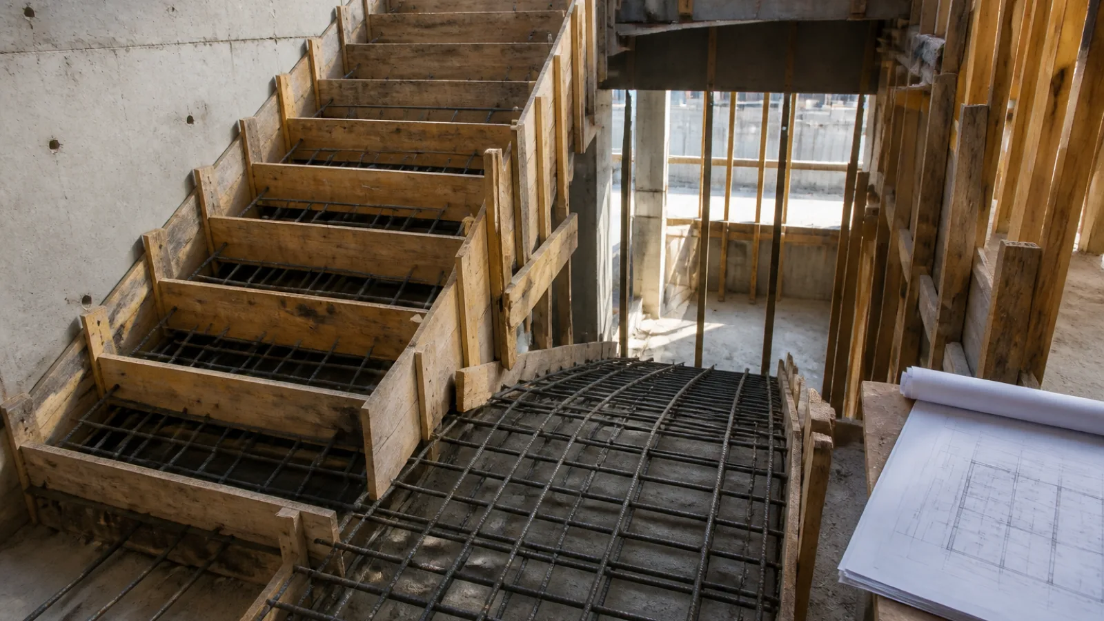
Structural staircase design combines architectural geometry, reinforced concrete design, load assessment, serviceability checks, detailing, and constructability. A staircase must be comfortable to use, safe under permanent and variable actions, robust at its supports, and detailed so that reinforcement can be fabricated and placed correctly.
This article presents a practical design workflow for straight, L-shaped, U-shaped, spiral, circular, curved, cantilever, floating, and precast concrete stairs. The numerical example is illustrative rather than a substitute for a project-specific design. Final designs must be checked against the governing building code, approved architectural drawings, geotechnical conditions, fire requirements, seismic provisions, and the directions of the responsible engineer.
For coordinated design, detailing, and construction documentation, a project team may also require specialist structural engineering services covering analysis models, reinforcement drawings, and BIM deliverables.
1. Design Basis and Engineering Responsibilities
Before starting staircase structural calculations, confirm the stair location, floor-to-floor height, available opening, clear width, headroom, finish build-up, handrail loads, support arrangement, fire rating, and access requirements. Identify whether the stair is part of a reinforced concrete frame, masonry structure, steel frame, or independent architectural feature.
The design standard should be stated clearly. A project in Europe may use Eurocode 2 for concrete design together with the relevant loading, fire, seismic, and national annex provisions. A project in the United States may use ACI 318 with the applicable building and loading standards. The principles are similar, but load combinations, minimum reinforcement, cover, anchorage, deflection limits, and detailing rules must not be mixed without engineering justification.
- Use the architectural dimensions as a starting point, but verify every bearing, opening, and level against structural drawings.
- Establish a continuous load path from treads and waist slab to landings, beams, walls, columns, and foundations.
- Separate conceptual sizing from final reinforcement design.
- Coordinate reinforcement with finishes, nosings, handrails, balustrades, MEP openings, and fire-stopping requirements.
- Obtain a qualified structural engineer's review before construction.
2. Types of Reinforced Concrete Staircases and Structural Behaviour
Straight reinforced concrete staircase
A straight stair commonly consists of a waist slab spanning between a lower support and an upper landing or beam. The slab acts primarily as a one-way inclined plate, with the main bending reinforcement running up the slope. Depending on the supports, it may be simply supported, continuous, or partially fixed. Straight stairs are efficient and easy to analyse, making them suitable for apartments, villas, schools, and many commercial buildings.
The principal limitations are the long uninterrupted flight, the space required for a comfortable rise and going, and the possibility of excessive vibration if the slab is too thin. A landing may be designed as part of the stair system or as an independent slab.
L-shaped staircase with landing
An L-shaped stair changes direction through approximately 90 degrees at an intermediate landing. Each flight usually transfers load to a landing beam, wall, or supporting slab. The landing can act as a horizontal slab, a folded plate, or a diaphragm tying the flights together. It improves circulation and can fit efficiently into a compact plan.
Designers must check the landing support, torsion at the inside corner, local effects at the flight-to-landing junction, and reinforcement continuity. If the landing is supported on walls on two sides, two-way action may be significant.
U-shaped staircase
A U-shaped or dog-leg stair has two parallel flights connected by an intermediate landing. It is common in apartments, high-rise cores, and emergency escape stairs because it provides a compact vertical circulation zone. Each flight can be analysed separately when the landing has direct support, although the complete system may develop continuity and torsional effects.
Typical support conditions include landing beams, core walls, edge beams, and half-landing slabs. The design must coordinate the central opening, clear headroom, balustrade loads, and reinforcement congestion around the landing supports.
Spiral staircase
A spiral stair wraps around a central post, circular stringer, central wall, or structural core. Its geometry creates three-dimensional load transfer. Treads may cantilever from a central column, span between an inner and outer stringer, or form part of a helical reinforced concrete shell.
Spiral staircase structural design requires more than a simple one-way slab calculation. Radial bending, circumferential bending, torsion, local shear, out-of-plane response, vibration, and connection forces should be considered. Spiral stairs are useful where space is limited, but they may be less suitable as the sole means of escape because of narrow inner treads and difficult movement of occupants or equipment.
Circular and curved staircase
A circular stair follows a constant-radius plan, while a curved stair may have a changing radius or a free-form architectural profile. These stairs can behave as curved beams, helical slabs, folded plates, or shells. Loads generate vertical bending, torsion, in-plane forces, and sometimes significant horizontal reactions at the supports.
Curved staircase structural analysis is best undertaken with a suitable three-dimensional model and then verified with simplified hand calculations. Mesh quality, support assumptions, local thickening, and the interpretation of shell forces are critical.
Cantilever staircase
In a cantilever stair, individual treads or a stair slab projects from a wall, spine beam, or concealed steel support. The fixed support must resist bending moment, shear, torsion, and often a substantial local anchorage force. The wall or spine must be checked for splitting, anchorage, punching, and construction-stage stability.
Cantilever staircase design is architecturally attractive, but the apparent simplicity can conceal demanding connection and serviceability requirements. Excessive deflection, vibration, cracking, or rotation at the wall can make the stair feel unsafe even when ultimate strength is adequate.
Floating staircase
A floating staircase is usually a visually minimal stair with concealed supports, open risers, or individually supported treads. Structurally, it may be a cantilever system, a central steel spine, side stringers, concealed brackets, or a combination of concrete and steel.
Floating staircase structural design must distinguish the architectural appearance from the actual load-bearing system. Every tread needs a defined load path, and the concealed support must accommodate construction tolerances, fire protection, vibration control, and inspection access.
Precast concrete staircase
Precast stairs may be manufactured as a single flight, a flight with landing, individual treads, or a complete stair module. They reduce site formwork and can improve dimensional consistency. Structural checks include lifting stresses, transportation, temporary bracing, bearing length, erection-stage stability, permanent loads, connections, and differential movement.
Precast stairs are particularly effective in repetitive apartment and high-rise developments. Connections must be shown clearly in the structural and shop drawings, including welds, bolts, dowels, grout pockets, bearings, and tolerance requirements.
3. Step-by-Step Structural Staircase Design Workflow
Step 1: Establish stair geometry
Start with the floor-to-floor height and select a comfortable riser and going. A common comfort relationship is approximately 2R + G = 600 to 650 mm, where R is riser height and G is going. This is a planning rule, not a structural requirement, and local codes may impose tighter limits.
For the illustrative example, use:
- Floor-to-floor height: 3.20 m.
- Stair width: 1.20 m.
- Twenty risers at 160 mm each.
- Nineteen goings at 280 mm, arranged as two flights with an intermediate landing.
- Concrete: C30/37.
- Reinforcement: B500B.
- Preliminary waist slab thickness: 180 mm.
- Nominal cover: 25 mm, subject to exposure, fire, durability, and code requirements.
For a dog-leg arrangement, use ten risers in each flight as a preliminary layout. The exact number of treads depends on the architectural convention at the landing and must be coordinated with finished floor levels.
Step 2: Calculate slope and effective span
For each flight, the vertical rise is 1.60 m and the horizontal run is approximately 2.52 m. The inclined length is therefore approximately √(1.60² + 2.52²) = 2.98 m. The slope angle is about 32.4 degrees and the cosine of the angle is approximately 0.844.
The design span depends on the support condition. For a simple preliminary check, use an effective span of 3.10 m measured along the flight between support centrelines. The final effective span must follow the applicable code and actual support geometry.
Step 3: Identify design actions
A staircase load calculation normally includes the self-weight of the inclined waist slab, concrete in the steps, finishes, partitions or infill, handrail and balustrade actions, imposed live load, and any concentrated loads required by the code. For a stair in a public or commercial building, the imposed load may be higher than for a private dwelling.
For an illustrative one-metre-wide strip, assume:
- Waist slab self-weight: 0.18 / 0.844 × 25 = approximately 5.33 kN/m² on plan.
- Step concrete allowance: approximately 1.00 kN/m².
- Floor finishes and screed: 0.75 kN/m².
- Characteristic permanent load, Gk: approximately 7.08 kN/m².
- Characteristic imposed load, Qk: 4.00 kN/m² for illustration.
These values are not universal. Step geometry, finishes, building use, code category, and local requirements can materially change them.
Step 4: Apply load combinations
Under a typical Eurocode ultimate limit state approach, an illustrative combination may be Ed = 1.35Gk + 1.50Qk. This gives approximately 1.35 × 7.08 + 1.50 × 4.00 = 15.56 kN/m². For a one-metre strip, the design line load is approximately 15.56 kN/m.
Under ACI 318 practice, the factored combination and load factors would be selected according to the adopted loading standard. Do not transfer Eurocode factors directly into an ACI calculation or vice versa.
Step 5: Calculate bending moment and shear
For a simply supported preliminary model, the staircase bending moment calculation is:
Med = wEdL² / 8
Using wEd = 15.56 kN/m and L = 3.10 m gives Med = 15.56 × 3.10² / 8 = approximately 18.7 kNm per metre width.
The corresponding support shear is:
Ved = wEdL / 2
Ved = 15.56 × 3.10 / 2 = approximately 24.1 kN per metre width. A continuous flight, landing restraint, or frame interaction can reduce positive midspan moment while increasing negative support moment and torsion. Those effects must be designed rather than assumed away.
Step 6: Select effective depth and calculate steel
Assume a 180 mm waist slab, 25 mm nominal cover, and 12 mm main bars. The effective depth is approximately d = 180 − 25 − 6 = 149 mm. Taking an internal lever arm z of approximately 0.9d = 134 mm and a design steel strength fyd of about 435 MPa for B500B, the required tension steel is:
As,req = Med / (fydz) = 18.7 × 10⁶ / (435 × 134) = approximately 321 mm²/m.
Subject to the governing code's minimum reinforcement and spacing rules, T12 bars at 250 mm centres provide approximately 452 mm²/m and would exceed this illustrative flexural requirement. The final selection may be T12 at 200 or 250 mm centres depending on crack control, anchorage, support moments, bar availability, and detailing continuity.
Provide distribution reinforcement across the stair width, for example T10 at 250 mm centres as an initial arrangement, subject to minimum steel rules. At the top and bottom supports, provide additional reinforcement for negative moments or local restraint where the structural model indicates it. Bars must be properly anchored into landing beams, walls, or slabs with the required development length.
Step 7: Check shear
The staircase shear force calculation begins with the design reaction and the critical section specified by the code, commonly near the face of the support or at a distance related to the effective depth. For a 180 mm slab and the illustrative reaction, concrete shear resistance will often exceed the applied shear, but this must be calculated using the actual longitudinal reinforcement ratio, concrete strength, size factor, axial effects, and code equations.
Do not assume that no links are required without checking local shear at supports, landing beams, concealed strings, openings, and concentrated reactions. If shear reinforcement is needed, it must be detailed so that it can actually be placed within the stair geometry.
Step 8: Check deflection, cracking, vibration, and robustness
A staircase deflection calculation may use span-to-effective-depth limits, a calculated serviceability deflection, or both. The service load combination should include the appropriate permanent and quasi-permanent imposed actions. Check the inclined slab, landing, cantilever noses, support rotation, and any concealed steel or bracket.
Serviceability is especially important for cantilever and floating stairs. Check crack width, vibration, walking comfort, differential movement, and the effect of finishes. Robustness provisions should ensure that the loss of a noncritical element does not cause disproportionate collapse, while fire design should verify cover, section dimensions, and fire resistance of the complete load path.
Step 9: Design landings and connections
Landings should not be treated as architectural gaps between flights. Design them for self-weight, finishes, imposed actions, support reactions, torsion, and the forces transferred from the flights. Check landing slabs for one-way or two-way action, punching or local shear where applicable, and compatibility with supporting beams or walls.
At a wall support, verify bearing, anchorage, splitting, local compression, and construction sequence. At a beam support, check the beam for the concentrated staircase reaction and torsional effects. At a precast connection, design the bearing pad, grout, dowels, welds, bolts, and temporary stability.
4. Staircase Reinforcement Detailing
Good staircase reinforcement detailing converts calculations into buildable reinforcement. Main flight bars generally run parallel to the slope and are placed near the tension face. Distribution bars run transversely across the stair width. Additional top bars are required over restrained supports, landings, and regions of negative moment.
- Show bar diameter, spacing, grade, shape, quantity, and mark.
- Maintain the specified cover using suitable spacers and chairs.
- Show anchorage and lap locations, avoiding congestion at supports and landings.
- Use closer spacing where crack control or local stress concentration requires it.
- Detail reinforcement around openings, edge beams, nosings, balustrade sockets, and embedded items.
- Identify which bars are continuous and which terminate with hooks, bends, or mechanical anchorage.
- Coordinate stair reinforcement with the landing and adjacent floor reinforcement.
A staircase rebar calculation should distinguish main flexural steel, distribution steel, support steel, edge bars, trimming bars, hanger bars, and any reinforcement required for torsion or local anchorage. Minimum steel and maximum spacing must be checked using the adopted code rather than copied from a generic detail.
5. Special Design Considerations for Spiral and Curved Stairs
For a spiral or curved stair, define the centreline radius, inner and outer radii, rise per revolution, tread angle, stair width, support locations, and load distribution. A simple radial strip can provide an initial estimate, but it does not capture the complete three-dimensional behaviour.
Use a three-dimensional shell, solid, or beam-and-shell model where appropriate. Review radial bending moments, circumferential moments, twisting moments, transverse shear, support reactions, and deflected shape. In a helical stair, membrane forces may develop, but they should not be relied upon unless the boundary conditions and shell action are reliable.
Spiral staircase reinforcement may include radial main bars, circumferential distribution bars, top and bottom reinforcement, edge reinforcement, and local bars around the central support. Reinforcement must follow the geometry without creating unacceptable bending radii or clashes. Circular staircase design also requires careful control of bar lengths, laps, cover, and construction joints.
6. Cantilever and Floating Staircase Design
For a cantilever tread, the basic bending moment at the fixed support can be estimated as M = PL + wL²/2 for a concentrated action P and uniform load w over the cantilever length L. This preliminary calculation must be expanded to include self-weight, finishes, handrail actions, torsion from eccentric loading, impact, and serviceability.
The fixed support often governs the design. Check the supporting wall or spine for flexure, shear, torsion, local bearing, anchorage breakout, splitting, and interaction with masonry or precast elements. Reinforcement should be developed sufficiently into the support, and the construction sequence must prevent premature loading before the concrete or connection reaches the specified strength.
For a floating stair, model the concealed spine or brackets as part of the complete structural system. Confirm that the visual gaps do not create unsupported edges, that the support is fire protected where required, and that deflection and vibration remain acceptable under repeated pedestrian loading.
7. Structural Analysis Software for Staircases
Software is valuable for complex stairs, but it does not replace engineering judgement. A model should be built only after the geometry, supports, materials, releases, load paths, and design assumptions have been defined.
Autodesk Robot Structural Analysis
Autodesk Robot Structural Analysis can be used for inclined beams, plates, shells, curved geometry, load combinations, reactions, and reinforcement design workflows. Use mesh refinement around landings, openings, supports, and abrupt changes in thickness. Verify local peaks rather than designing directly from a singularity.
ETABS staircase modeling
ETABS is useful when stairs interact with a building frame, core walls, diaphragms, and seismic load paths. Model stairs as slabs, shell elements, or equivalent members according to their actual behaviour. Avoid unintentionally adding excessive stiffness to the building by checking diaphragm assignments, connectivity, and end releases.
SAP2000 staircase analysis
SAP2000 can model straight, curved, spiral, and floating stairs using frame, shell, and solid elements. It is particularly useful for reviewing three-dimensional reactions, torsion, support forces, and construction-stage cases. Use realistic restraints and confirm the local axes of shell elements before interpreting results.
SAFE staircase design
SAFE is often used for slab and foundation systems, but it can also assist with landing and stair slab analysis where the geometry and support conditions are compatible. Review the limitations of the model when representing inclined or helical elements, and verify that load transfer to the supporting structure is correctly represented.
Revit structural staircase modeling and BIM
Revit supports coordinated BIM staircase design, architectural geometry, structural framing, reinforcement layout, schedules, and clash detection. Revit should be connected to an analytical model or design software where required. A visually complete model is not automatically a structurally valid model.
For all platforms, perform independent checks using reactions, tributary loads, hand calculations, equilibrium, and expected deflected shapes. Review model warnings, mesh distortion, excessive stiffness, disconnected nodes, accidental restraints, and unrealistic hinges.
8. Staircase Structural Drawings and Shop Drawings
A staircase reinforcement drawing should communicate geometry and reinforcement without relying on assumptions. Include plans, longitudinal sections, cross-sections, landing details, support details, enlarged connection details, bar marks, cover notes, material grades, construction joints, and references to the design drawings.
Typical staircase shop drawings include:
- Finished floor levels, structural levels, riser and tread dimensions.
- Flight width, clear headroom, landing dimensions, and openings.
- Waist slab thickness and step profile.
- Main bottom reinforcement, top support reinforcement, distribution bars, edge bars, and trimming bars.
- Bar diameters, spacing, shapes, lengths, laps, hooks, couplers, and anchorage.
- Concrete grade, reinforcement grade, cover, construction tolerances, and casting sequence.
- Interfaces with beams, walls, slabs, columns, balustrades, handrails, finishes, and embedded items.
- Sections through typical and congested areas.
AutoCAD staircase shop drawings remain common for fabrication and site use, while BIM staircase design can produce coordinated views, schedules, and model-based quantities. The drawing should be reviewed against the latest architectural and structural revisions before issuing it for construction.
9. Bar Bending Schedule and Quantity Estimation
A staircase bar bending schedule should list each bar mark, diameter, shape code, number, cut length, total length, mass, and location. Include main flight bars, distribution bars, landing bars, support bars, edge reinforcement, trimming bars, and any dowels or starter bars.
For staircase rebar quantity estimation, calculate the total bar length from the schedule and multiply by the unit mass of each diameter. Add approved allowances for laps, hooks, couplers, waste, and fabrication, but do not hide excessive waste inside a general percentage. Concrete quantities should be calculated separately for the waist slab, steps, landings, edge beams, and local thickenings.
Quantities taken directly from a three-dimensional model should be checked against drawings and the design intent. Model-based quantities can be wrong when overlapping concrete, joined geometry, duplicated bars, or unmodelled laps are present.
10. Common Design and Detailing Errors
- Designing the stair only for vertical gravity loads while ignoring torsion, support rotation, or horizontal forces.
- Using the sloping plan length incorrectly when calculating slab self-weight or effective span.
- Failing to include finishes, step concrete, balustrade loads, or construction-stage actions.
- Providing main bars without adequate development into the landing or support.
- Using generic reinforcement details that do not satisfy the selected code or actual support condition.
- Ignoring negative moments at restrained landings and walls.
- Allowing reinforcement clashes at the flight-to-landing junction.
- Relying on software colour contours without checking equilibrium and local force peaks.
- Omitting deflection, cracking, vibration, fire resistance, and durability checks.
- Issuing shop drawings that do not match the latest architectural levels and openings.
11. Final Design Review Checklist
- Are riser, going, width, headroom, landings, and finished levels compliant with the applicable code?
- Are all permanent, imposed, concentrated, handrail, partition, and construction loads included?
- Are load combinations and material factors consistent with one design standard?
- Are bending, shear, torsion, bearing, punching, deflection, crack width, vibration, fire, and robustness checks complete?
- Does the support structure safely resist the staircase reactions and connection forces?
- Are reinforcement diameter, spacing, cover, anchorage, laps, and development lengths shown?
- Do the reinforcement drawings, shop drawings, bar bending schedule, and BIM model agree?
- Has the final package been independently reviewed and approved by the responsible structural engineer?
A reliable reinforced concrete staircase design is the result of coordinated geometry, transparent assumptions, appropriate analysis, code-compliant reinforcement, and clear construction documentation. Straight flights may be designed efficiently with hand calculations, while spiral, curved, cantilever, floating, and heavily integrated stairs require more detailed three-dimensional analysis and connection design.