Excavation Support Monitoring: Inclinometers, Survey Points, Crack Gauges, and Trigger Levels
A reliable excavation support monitoring program connects baseline surveys, appropriate instruments, regular data review, and predefined responses. This guide explains how to monitor retaining systems, adjacent structures, groundwater, and construction changes without treating monitoring as a substitute for engineering or site controls.
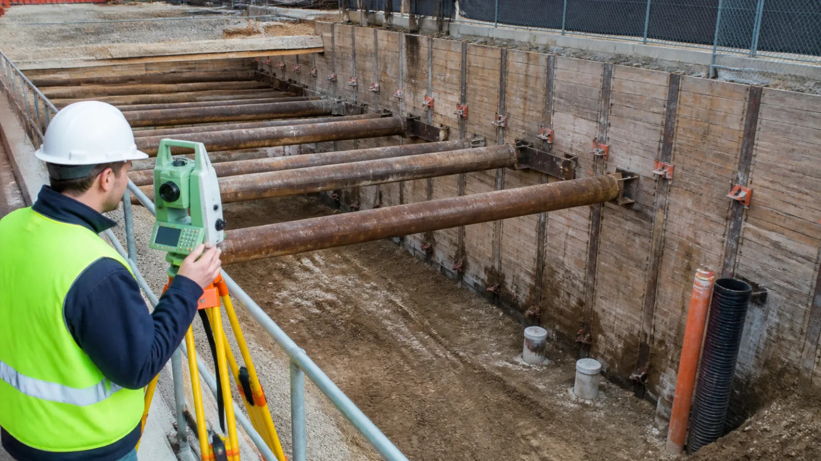
Excavation work can change the stresses, groundwater conditions, and support provided by the ground. Movement may affect retaining walls, soldier piles, diaphragm walls, sheet piles, braced excavations, anchors, adjacent foundations, pavements, utilities, and public areas. Excavation support monitoring provides a structured way to identify changes early and support decisions during construction. It does not, however, replace competent engineering design, field inspections, construction controls, or emergency planning.
A sound program combines baseline measurements, visual observation, carefully selected instruments, data review, defined trigger levels, and predetermined responses. Available geotechnical monitoring instrumentation includes tools for measuring deformation, settlement, cracking, groundwater pressure, and structural loads. The instruments are useful only when they are installed correctly, read at appropriate intervals, and interpreted in the context of the excavation sequence and site conditions.
What Is Excavation Support Monitoring?
Excavation support monitoring is the planned collection and interpretation of measurements that show how a shoring system, surrounding ground, groundwater regime, and nearby structures are performing during construction. It compares actual behavior with expected behavior and provides information for managing risk as excavation progresses.
Design calculations describe anticipated performance under defined assumptions. Monitoring observes what is actually happening in the field. The two functions are related but not interchangeable. A reading may confirm design expectations, reveal a trend that requires attention, or show that construction conditions differ from the assumptions used in design.
Different measurements describe different conditions:
- Movement is a change in position, such as wall translation or ground settlement.
- Deformation describes a change in shape, curvature, tilt, or distribution of movement through a wall or soil mass.
- Settlement is downward vertical movement of ground, a pavement, slab, or foundation.
- Pore-water pressure is the pressure carried by water within soil voids. Changes can indicate drawdown, seepage, or altered hydraulic gradients.
- Cracking is visible evidence of distress or movement at a particular location, but a crack alone does not establish its cause.
- Structural condition includes the state of braces, anchors, connections, walls, foundations, and other load-carrying components.
Monitoring objectives should be tied to credible failure or damage mechanisms. For example, a deep excavation beside a brittle masonry building may require close attention to differential settlement and crack-width changes, while a flexible anchored wall may require subsurface inclinometer readings, survey points, anchor-load measurements, and groundwater observations.
How to Build an Excavation Monitoring Plan
1. Establish the baseline condition
Before demolition, excavation, dewatering, or installation of support systems, document the existing condition. A preconstruction survey should identify visible cracks, out-of-plumb walls, settlement indicators, pavement defects, utility features, and other conditions that could later be confused with construction-related effects.
Useful baseline records may include dated photographs, crack maps, condition surveys of adjacent buildings, existing benchmark locations, utility documentation, and initial groundwater observations. Baseline readings should be taken from installed instruments where practical, or from established survey points before construction changes the site. The survey control itself must be checked for stability; a benchmark that moves with the affected ground cannot provide a reliable reference.
2. Identify instruments and monitoring locations
Sensor placement should reflect wall geometry, excavation stages, soil variability, adjacent structures, surcharge loads, and likely movement patterns. Instruments placed only at convenient locations may miss the governing response. Locations near corners, changes in wall stiffness, transitions in support, deep cuts, sensitive foundations, utilities, or heavy traffic may require particular consideration.
The monitoring layout should also account for installation sequence. Some instruments must be installed before excavation to establish a meaningful baseline. The plan should identify each instrument, its coordinate or station, installation details, datum, expected measurement direction, access requirements, and protection against damage from equipment or site traffic.
3. Set reading frequency and data responsibilities
Reading frequency should change with construction risk. Baseline readings may be taken over multiple observations to establish repeatability. More frequent measurements are commonly needed during excavation advances, brace installation or removal, anchor stressing, dewatering changes, backfilling, and other transitions. Frequency should also increase if movement rates rise or adjacent conditions deteriorate.
Manual readings can be effective when access is reliable and a qualified person can review the results promptly. Automated systems can provide more frequent data and after-hours alerts, but they require reliable power, communications, calibration, maintenance, and human review. The plan should name the monitoring coordinator, data reviewer, engineer responsible for interpretation, person authorized to stop work, and after-hours contacts.
Data quality checks should identify missing readings, improbable changes, sensor errors, unstable control points, and inconsistent instrument orientation. An alert should never be accepted or dismissed solely because it arrived through an automated system.
4. Connect readings to a response plan
A trigger action response plan (TARP) links defined conditions to named actions. It should state who receives alerts, who verifies readings, who has authority to pause or stop work, how stakeholders are notified, and what temporary controls are available. The plan should be reviewed before construction and updated when the sequence, design, instrumentation, or site conditions change.
Core Instruments Used in Excavation Support Monitoring
| Instrument | Primary measurement | Typical purpose | Important limitations |
|---|---|---|---|
| Inclinometers | Lateral subsurface movement | Track deformation in or behind retaining walls and through the soil profile | Require stable casing, correct survey direction, reliable baseline readings, and interpretation of cumulative displacement |
| Survey prisms or robotic total-station points | Three-dimensional surface movement | Monitor walls, structures, pavements, and other visible targets | Need line of sight and stable control; atmospheric effects, prism damage, or control-point movement can affect results |
| Settlement points and precise leveling | Vertical movement | Track ground, slabs, roads, and adjacent foundations | Depends on stable benchmarks and can miss localized or nonvertical movement |
| Crack gauges or tell-tales | Change in crack width or displacement | Document movement at visible cracks in buildings, walls, or pavements | Indicate change at a crack but do not independently diagnose the cause |
| Piezometers | Pore-water pressure | Monitor drawdown, seepage, hydraulic gradients, and groundwater response | Readings require proper installation, stabilization, and interpretation alongside deformation data |
| Load cells, anchor instrumentation, or strut gauges | Force or load change | Observe behavior of braces, struts, tiebacks, and other support elements where appropriate | Load changes require qualified interpretation and may reflect temperature, installation, redistribution, or damage |
Inclinometers are commonly installed in grooved casings within or behind a retaining system. A probe is lowered through the casing to measure lateral deviation at successive depths. Initial readings establish the casing profile and reference direction; later profiles are compared with that baseline to calculate incremental and cumulative displacement. Installation damage, casing distortion, incorrect probe orientation, or an unstable reference can produce misleading results.
Survey prisms and robotic total stations can measure movement in three dimensions, including horizontal displacement, vertical movement, and sometimes changes in orientation. The monitoring team must distinguish target movement from movement of the instrument or control points. Temperature, atmospheric refraction, line-of-sight obstructions, and loose or damaged prisms can affect precision.
Settlement points and precise leveling provide information about vertical movement and differential settlement. They are especially useful around sensitive foundations, pavements, slabs, and utility corridors. Results are meaningful only when the benchmark network remains stable and the survey method is consistent.
Crack gauges, also called tell-tales, measure change across a visible crack. They are valuable for documenting whether a crack is opening, closing, or shifting, but they do not by themselves determine whether the cause is excavation, thermal movement, pre-existing distress, vibration, or another mechanism.
Piezometers measure pore-water pressure. Groundwater readings should be reviewed with excavation depth, pumping rates, rainfall, seepage observations, and deformation data. A change in water pressure may precede or accompany movement, but the relationship is site-specific.
Load cells, anchor instrumentation, and strut gauges can help identify changes in support force. Because measured force may be affected by stressing procedures, temperature, redistribution, connection behavior, or instrument condition, qualified engineers should interpret these readings rather than applying a simple pass-or-fail rule.
Choosing Instruments for Different Excavation Risks
Instrumentation should be selected from the credible failure modes, not from a standard checklist. The retaining system, soil profile, groundwater conditions, construction sequence, and consequences of movement determine what needs to be measured.
| Risk or concern | Potential measurements | Examples of systems or locations |
|---|---|---|
| Wall deflection or rotation | Inclinometers, survey prisms, visual inspections | Retaining walls, soldier piles and lagging, diaphragm walls, sheet piles |
| Ground settlement | Settlement points, precise leveling, survey points | Ground behind walls, roads, sidewalks, utility corridors |
| Adjacent building movement | Prisms, precise leveling, tilt observations, crack gauges | Foundations, façades, columns, slabs, party walls |
| Cracking or localized distress | Crack gauges, photographs, visual inspections | Masonry, concrete, pavement, retaining structures |
| Groundwater change | Piezometers, water-level observations, flow or pumping records | Excavation base, surrounding soil, nearby wells or basements |
| Brace or anchor load change | Load cells, anchor instrumentation, strut gauges, inspections | Internally braced or anchored excavations |
Retaining walls, soldier piles and lagging, diaphragm walls, and sheet piles respond differently because their stiffness, continuity, joints, installation methods, and support conditions differ. Internally braced and anchored systems also experience changes during stressing, preload transfer, brace removal, and load redistribution. These differences affect instrument selection and the timing of readings. The matrix above is a planning aid, not a universal design requirement.
Trigger Levels: Alert, Action, and Stop-Work Conditions
A monitoring plan should define terminology before construction begins. A baseline is the established initial condition and its expected measurement variability. A threshold is a project-specific criterion used to judge a reading or trend. An alert level generally prompts verification, notification, and closer review. An action level requires a defined mitigation or construction change. A stop-work or emergency level indicates that work should be paused, the affected area controlled, and urgent engineering or emergency procedures initiated.
Trigger levels may be based on absolute movement, movement rate, acceleration, differential movement, crack-width change, pore-pressure change, structural load change, or combinations of measurements. Trend and rate can be more important than one isolated reading. A series of small readings that consistently accelerates may warrant action even if no single reading is large.
Project-specific thresholds should account for design predictions, tolerable movement, adjacent-structure sensitivity, measurement precision, data uncertainty, construction stage, and the consequences of exceedance. The engineer of record or qualified geotechnical professional should establish and periodically review the criteria. Universal numerical limits are inappropriate because the same movement may be tolerable in one setting and damaging in another.
| Level | Meaning | Verification | Typical response |
|---|---|---|---|
| Baseline or normal range | Measurements are consistent with the established condition and expected construction response | Routine quality checks and trend review | Continue planned work and monitoring |
| Alert | A reading, rate, or trend requires attention but may be within measurement or construction variability | Repeat the reading, check controls and instruments, and inspect the area | Notify designated reviewers, increase review or reading frequency, and assess conditions |
| Action | Movement or another condition may exceed the accepted project response | Confirm independently and review construction and engineering records | Implement the TARP, restrict relevant activities, and apply engineered mitigation |
| Stop-work or emergency | Potential imminent harm, uncontrolled movement, severe distress, or unreliable support condition | Verify if safe, without delaying protective action | Stop or isolate affected work, secure the area, notify emergency contacts, and obtain urgent engineering direction |
This conceptual table is illustrative only. It does not provide universal numerical limits and must not replace project-specific engineering criteria or emergency procedures.
How to Respond When a Trigger Is Reached
Verify the reading
Repeat the measurement where safe and appropriate. Check the instrument, installation, probe orientation, calibration status, battery or power supply, communications, and data-transmission record. For survey data, check the instrument setup, backsight, atmospheric conditions, and control points. Compare with an independent measurement when practical, and perform a visual inspection for wall movement, cracking, seepage, exposed soil, damaged supports, or other distress.
Assess the trend and surrounding conditions
Review excavation depth, recent bracing or anchor work, anchor stressing, pumping or dewatering, rainfall, surcharge changes, nearby traffic, utility work, vibration, soil exposure, and changes in the construction sequence. Compare the reading with earlier results, not just the immediately preceding value. Correlated changes across inclinometers, prisms, settlement points, crack gauges, and piezometers generally provide more useful context than an isolated result.
Apply the planned response
Depending on the TARP and engineering direction, responses may include increasing reading frequency, adding survey points, restricting loads or traffic, pausing excavation, controlling water, stabilizing exposed soil, or notifying owners, utilities, public agencies, and affected occupants. Bracing should be installed, adjusted, or supplemented only under qualified engineering direction. If conditions indicate an immediate threat, isolate or evacuate the affected area and activate emergency procedures.
Document decisions and close the event
Maintain time-stamped records of readings, instrument IDs, photographs, notifications, inspections, engineering decisions, corrective measures, and changes to the work sequence. An event should be closed only after the responsible professionals confirm that the cause has been addressed, monitoring shows an acceptable trend, and any revised controls or thresholds have been communicated.
Reporting and Data Review Practices
A useful daily or periodic monitoring report should include a site plan with instrument locations, the latest readings, cumulative movement, rate of change, baseline comparison, trigger status, missing or rejected data, relevant charts, photographs, weather or construction notes, and required actions. Reports should identify the reporting period, data source, coordinate system, datum, reviewer, and any limitations.
Preserve raw readings as well as processed results so that calculations and decisions can be audited. Automated alerts improve speed but still require human review. Consistent coordinate systems, stable datum control, calibration records, sensor maintenance, redundant measurements, and documented data validation help distinguish real site behavior from instrumentation or processing errors.
Common Mistakes in Excavation Monitoring
- Installing instruments after excavation has already begun, making the baseline incomplete or impossible to establish.
- Selecting instruments without first identifying the governing risk or likely movement mechanism.
- Using unstable survey benchmarks or control points.
- Treating a single reading as conclusive without checking the instrument, trend, and surrounding conditions.
- Setting thresholds without considering measurement uncertainty and precision.
- Collecting data without assigning a reviewer or response authority.
- Failing to monitor during transitions such as deeper excavation, brace removal, anchor stressing, backfilling, or changes in dewatering.
- Continuing work after an unexplained trend without engineering review.
Practical Checklist for Owners and Contractors
- Identify the responsible engineer and monitoring coordinator.
- Complete preconstruction condition documentation, photographs, crack mapping, and utility records.
- Document instrument locations, installation details, reference points, and protection measures.
- Establish baseline readings and verify survey control and datum stability.
- Set reading frequency for each construction phase and transition.
- Issue a trigger action response plan with a current contact list.
- Define the reporting format, review process, and distribution.
- Assign inspection, calibration, maintenance, and damage-replacement responsibilities.
- Confirm stop-work authority and emergency procedures.
- Plan final monitoring, demobilization, data archiving, and record retention.
Frequently Asked Questions
How often should an excavation support system be monitored?
Frequency depends on the excavation stage, risk level, instrument type, movement rate, adjacent-structure sensitivity, and the project-specific monitoring plan. Readings are typically more frequent during active excavation and transitions such as support installation, dewatering changes, brace removal, and backfilling. The responsible professionals should increase frequency when trends change.
Are inclinometers enough to monitor an excavation?
No. Inclinometers are valuable for measuring subsurface lateral movement, but they do not show every relevant condition. Depending on the risks, they should be combined with surface survey points, settlement monitoring, structural observations, crack gauges, groundwater measurements, load instruments, and visual inspections.
What is the difference between an alert level and an action level?
An alert level generally prompts verification, notification, and closer review. An action level requires a defined mitigation, restriction, or construction change under the monitoring plan. Terminology varies by project, so the meanings and required responses should be written clearly in the TARP.
Can crack gauges prove that an excavation caused building damage?
No. Crack gauges document change in width or displacement at a particular crack. Determining causation requires correlation with timing, location, excavation movement, settlement, groundwater data, construction activity, preconstruction condition, and professional assessment.
Who should establish excavation monitoring trigger levels?
Qualified project professionals, typically under the direction of the engineer of record or geotechnical engineer, should establish and periodically review trigger levels. Criteria should reflect design predictions, measurement uncertainty, construction stages, adjacent-structure sensitivity, and the consequences of exceedance.
Conclusion
Effective excavation support monitoring links the right instruments to credible risks, reliable baselines, meaningful trigger levels, disciplined reporting, and prompt action. Inclinometers, survey points, settlement points, crack gauges, piezometers, and load instruments each reveal different aspects of site performance; none should be treated as a complete monitoring system by itself.
Monitoring is one component of a broader excavation safety and quality-control system. Competent design, inspections, construction controls, groundwater management, communication, and emergency planning remain essential to managing excavation risk.