Machine Vision Inspection Systems: Cameras, Lighting, AI, and Factory Quality Control
Machine vision inspection systems combine cameras, optics, lighting, software, and production controls to evaluate parts and products automatically. This guide explains the complete workflow, compares rule-based and AI vision, and outlines the practical requirements for reliable factory quality control.
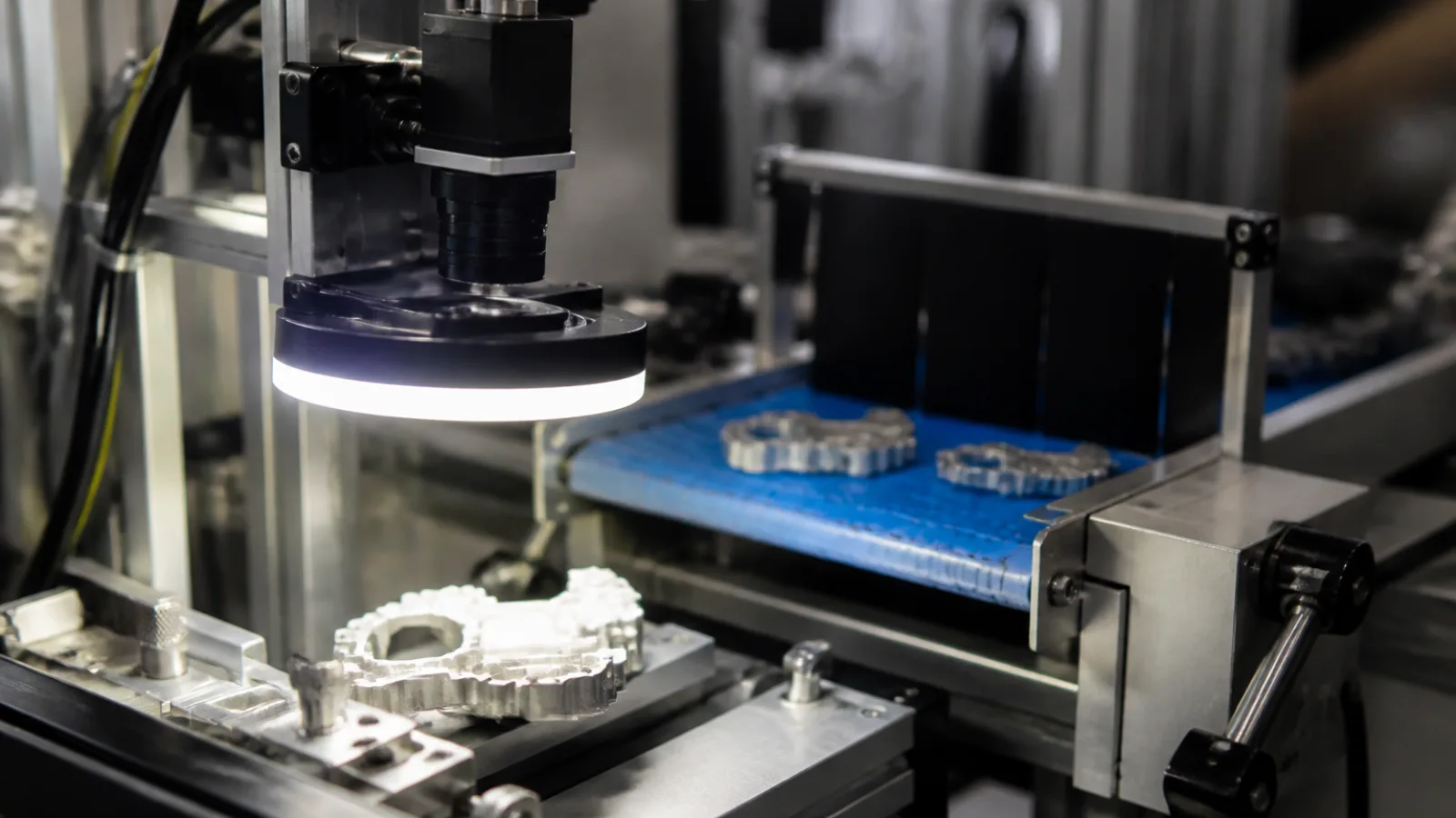
Machine vision inspection systems use controlled image capture and software analysis to evaluate parts, products, packaging, and processes on a production line. A complete system does more than take photographs: it presents the part consistently, creates a usable image, analyzes defined features, makes a quality decision, and communicates that decision to factory equipment.
For engineers and quality teams evaluating machine vision inspection systems, the important question is not simply which camera to buy. Reliable performance depends on the relationship between optics, machine vision lighting, triggering, software, mechanical presentation, rejection controls, and production data. The following guide explains how those elements work together and where automated visual inspection is most effective.
What Are Machine Vision Inspection Systems?
In practical manufacturing terms, a machine vision inspection system is an automated quality-control station that captures images of a part or product and evaluates them against defined requirements. The system may check whether a component is present, measure a feature, verify an assembly, read a code, or identify a surface defect.
The basic sequence is straightforward:
- Present the part in a controlled position.
- Capture one or more images.
- Process the image and extract relevant features.
- Compare the results with specifications or learned examples.
- Make a pass/fail or classification decision.
- Send the result to a PLC, robot, reject device, operator interface, or factory database.
Machine vision differs from an ordinary security camera because it is designed for controlled imaging and measurable decisions rather than general observation. A barcode reader is optimized for decoding one type of symbol, while a vision system can combine code reading with dimensional, assembly, and surface checks. A photoelectric sensor generally detects presence or position at one point; a vision system analyzes many pixels and can evaluate shape, location, contrast, and appearance across an entire field of view.
How a Machine Vision Inspection System Works
A dependable inspection is a coordinated workflow. The following steps show how machine vision systems typically operate on a production line.
- Part positioning and presentation: Conveyors, nests, guides, escapements, robots, or indexing mechanisms place the part within the camera’s field of view. Repeatable orientation and spacing reduce variation in the image.
- Triggering and image capture: A photoelectric sensor, encoder, PLC signal, robot position, or timed event tells the camera when to acquire an image. The exposure must occur at the correct location and duration.
- Lighting and image formation: The light source is selected to make the target feature visible while reducing glare, shadows, texture, and background distractions. The camera, lens, and lighting together determine the quality of the image.
- Image processing and feature extraction: Software may correct brightness, filter noise, locate a pattern, measure an edge, identify a region, or extract characters, shapes, colors, or surface information.
- Rule-based or AI-based classification: The system applies measurement limits, geometric rules, pattern criteria, or a trained model to determine whether the result is acceptable.
- Decision communication and rejection: A pass or fail signal is sent to a PLC, robot, diverter, air jet, stop mechanism, alarm, or operator display. The timing of this signal must correspond to the correct physical part.
- Data recording and feedback: Results can be associated with timestamps, lot numbers, product recipes, defect categories, images, and traceability records. Trends may reveal tool wear, process drift, or recurring defects.
Repeatable presentation, stable timing, and consistent imaging matter as much as the algorithm. A powerful model cannot reliably compensate for motion blur, changing part position, glare, or an inconsistent trigger. In many projects, improving the mechanical and optical conditions produces a greater benefit than changing the inspection software.
Core Components of a Machine Vision System
Cameras and Image Sensors
Industrial cameras convert light into digital image data. An area-scan camera captures a two-dimensional frame and is suitable for most discrete parts, assemblies, and packages. A line-scan camera captures one line at a time while the part or web moves past it, making it useful for continuous materials, wide surfaces, rolls, and high-speed inspection.
Resolution determines how many pixels represent the field of view. The required resolution depends on the smallest defect or dimensional change that must be detected, the contrast of that feature, and the measurement tolerance. A larger field of view spreads available pixels over more area, so a small defect may occupy too few pixels to evaluate reliably. Higher resolution alone does not guarantee performance if the lens, lighting, focus, exposure, or motion control is inadequate.
Frame rate affects how quickly images can be acquired, while exposure time affects brightness and motion blur. Monochrome cameras often provide strong sensitivity and are useful when shape, contrast, or intensity is the primary concern. Color cameras are appropriate when color differences or product identification are important, but they may require more controlled illumination and processing.
Lenses and Optics
The lens determines how the scene is projected onto the sensor. Important selection factors include field of view, working distance, focal length, depth of field, distortion, sensor format, and the available mounting space.
Field of view must be large enough to contain the inspection area but not so large that critical features become too small. Working distance is the space between the lens and the part. Depth of field describes the range over which the part remains acceptably sharp when its position varies. A shallow depth of field can create inconsistent results on parts with height variation.
Distortion can affect dimensional measurements and edge locations, especially near the edge of the image. Lens selection and calibration can reduce this problem. In some applications, telecentric optics are used to minimize perspective changes when measuring components with varying height or when dimensional accuracy is especially important. The lens is not just an accessory; it directly affects whether a defect is visible and whether a measurement is trustworthy.
Lighting for Machine Vision Inspection
Machine vision lighting is often the decisive factor in inspection performance. The goal is to create a repeatable image with strong contrast between the feature of interest and its background while suppressing unwanted reflections, texture, and shadows.
- Backlighting: Places the part between the light and camera to create a silhouette. It is useful for outlines, gaps, openings, profiles, and dimensional checks.
- Front or bright-field lighting: Illuminates the visible surface from the camera direction and can reveal general shape, print, color, and surface features.
- Dark-field lighting: Directs light at a low angle so scratches, raised edges, burrs, and other surface changes scatter light into the camera.
- Diffuse lighting: Produces broad, even illumination and helps reduce harsh reflections on curved, glossy, or irregular surfaces.
- Coaxial lighting: Sends light along the optical axis and is useful for flat reflective surfaces, markings, and certain measurement applications.
- Structured or polarized lighting: Uses controlled patterns or polarization to separate surface shape, suppress glare, or improve contrast on difficult materials.
Lighting should be designed around the defect and material, not selected as a general-purpose add-on. The same part may require different lighting for a dimension check, a scratch inspection, and a printed-character check.
Triggers, Sensors, and Timing
Triggers coordinate image acquisition with part movement. A photoelectric sensor can detect the leading edge of a product, while an encoder-based trigger can generate image events at fixed travel distances on a conveyor. PLC signals, robot positions, or indexing mechanisms may also initiate capture.
Strobe timing can freeze motion and provide consistent light intensity, but the pulse, exposure, conveyor speed, and camera readout must be coordinated. If acquisition occurs too early or too late, the image may contain the wrong part or the wrong region. If the exposure is too long for the line speed, motion blur can obscure small defects. Timing logic should also account for the distance between the inspection point and the rejection point.
Processing Hardware and Vision Software
Processing may run in a smart camera, a dedicated vision controller, or an industrial computer located near the line. Edge processing allows decisions to be made close to the equipment and can reduce dependence on remote systems.
Vision software commonly provides image preprocessing, filtering, measurement tools, pattern matching, optical character recognition, optical character verification, barcode reading, geometric checks, color analysis, and pass/fail logic. Preprocessing can improve contrast or reduce noise, but excessive filtering may also remove meaningful defect information. The inspection should therefore use the simplest processing approach that meets the requirement and can be maintained by the plant team.
Rejection Mechanisms and Line Controls
Inspection results can activate air jets, mechanical diverters, conveyor stops, robotic handling, alarms, or operator prompts. The choice depends on product size, line speed, part value, safety requirements, and whether the rejected item must be preserved for review.
Reject confirmation is important. A system may use a downstream sensor, camera, or position check to confirm that the failed part was actually removed. Safe failure behavior should be defined for lost communication, camera faults, sensor failures, and uncertain decisions. Bad parts must not continue downstream simply because an inspection result was missed or a reject actuator did not respond.
Rule-Based Vision Versus AI Vision Inspection
Traditional machine vision tools and AI vision inspection solve different types of problems. Rule-based tools are often the strongest choice when the requirement is stable, measurable, and clearly defined. Machine learning or deep-learning methods can be useful when appearance varies and the decision depends on complex visual patterns.
| Approach | Strengths | Best-fit applications | Limitations |
|---|---|---|---|
| Rule-based vision | Deterministic logic, measurable limits, explainable results, and straightforward validation | Presence, position, dimensions, orientation, clear edges, barcodes, and defined surface defects | Can be sensitive to changes in lighting, presentation, texture, and acceptable appearance variation |
| AI or deep-learning vision | Handles variable appearance and can classify complex or subtle visual patterns | Cosmetic grading, variable textures, complex defects, and acceptable-versus-unacceptable appearance classification | Requires representative training and validation data, ongoing monitoring, and careful control of false positives and false negatives |
AI does not remove the need for good optics, lighting, triggering, and process control. A model trained on poor or unrepresentative images may produce unreliable results. Training data should include normal production variation, different lots, realistic defect types, and examples near the acceptance boundary. The result also needs a defined validation method and a process for handling new defect modes.
What Can Machine Vision Inspect?
Machine vision can support many inspection tasks, provided the relevant feature is visible and the production conditions are controlled. Representative applications include:
- Presence, absence, and correct assembly of components
- Dimensions, alignment, orientation, position, and surface geometry
- Scratches, cracks, contamination, dents, burrs, chips, and cosmetic defects
- Labels, print quality, characters, barcodes, and traceability marks
- Packaging seals, fill levels, closures, caps, and product counts
- Color, shape, component identity, and product configuration
Achievable results depend on defect contrast, part variability, production speed, tolerance, material, surface finish, and camera access. A crack hidden behind another component cannot be inspected from an obstructed viewpoint. A transparent container may require specialized lighting and background control. A cosmetic standard that is obvious to a trained person may need carefully defined samples and consistent illumination before software can classify it.
Calibration, Validation, and Accuracy Limits
Calibration establishes the relationship between image measurements and real-world units. Pixel-to-real-world calibration can support dimensional checks, while lens distortion correction improves accuracy across the field of view. Reference standards, known dimensions, and stable fixtures help verify that the system continues to measure correctly.
Validation should define tolerance limits, golden samples, acceptable variation, and the consequences of false decisions. A false positive rejects a good part; a false negative allows a defective part to pass. The acceptable balance depends on product risk, downstream controls, material cost, and customer requirements.
Practical limits include:
- Occlusion or limited access to the feature
- Reflective, transparent, translucent, or highly textured surfaces
- Changing ambient light or unstable illumination
- Vibration, movement, and inconsistent part presentation
- Lens or window contamination
- Defects smaller than the effective optical resolution
Inspection repeatability should be tested over time, across shifts, lots, operators, temperatures, and realistic production speeds. Validation against ideal samples alone is not sufficient. The test set should include good parts with normal variation, known bad parts, borderline examples, and likely process changes.
Integrating Vision Inspection With Factory Systems
Vision systems commonly exchange signals and data with PLCs, robot controllers, conveyors, MES platforms, SCADA systems, quality databases, and traceability software. Industrial communication interfaces may include discrete I/O, industrial Ethernet, fieldbus connections, or vendor-supported application interfaces.
Useful inspection data may include:
- Pass or fail status
- Defect category and location
- Image identifier or stored image
- Timestamp and station identifier
- Product, recipe, serial, or lot number
- Measurement values and confidence score where appropriate
Integration should define ownership of the inspection decision, reject timing, alarms, recipes, user permissions, and audit records. The PLC may own line sequencing while the vision system owns image analysis, but the boundary must be explicit. Recipe changes should be controlled so that the camera, lighting, limits, and downstream equipment use matching settings.
How to Decide Whether Machine Vision Fits a Production Line
A practical evaluation should begin with the inspection requirement rather than a preferred camera or software brand. Consider the following questions:
- What must be inspected? Define the defect, characteristic, location, and acceptance criteria in measurable terms.
- What tolerance and minimum defect size apply? Establish the smallest feature or variation that must be detected.
- What is the production speed? Confirm the available inspection time, image rate, processing time, and reject window.
- How repeatable is part presentation? Assess orientation, spacing, height, vibration, and the need for nests or guides.
- What are the lighting and material constraints? Consider reflectivity, transparency, texture, color, ambient light, and camera access.
- What false-reject and escape rates are acceptable? Set targets based on product risk and the cost of each type of error.
- Are representative samples available? Collect good parts, known defects, borderline examples, and natural production variation.
- What integration and reporting are required? Define PLC signals, reject confirmation, traceability, images, alarms, and quality records.
- How will the system be maintained? Plan lens and light cleaning, recipe changeover, calibration checks, spare parts, and operator training.
- Does the economics support the project? Compare equipment and integration cost with manual inspection, scrap, rework, warranty exposure, and possible process improvements.
A proof of concept is appropriate when the feature is difficult to image, the acceptable variation is unclear, AI may be required, or the production speed leaves little margin. A meaningful test should use representative equipment, optics, lighting, part presentation, and timing. It should measure detection performance, false rejects, processing time, repeatability, image quality, changeover effort, and the system’s response to realistic variation. A laboratory demonstration using carefully positioned sample parts is not enough to approve a production installation.
Frequently Asked Questions About Machine Vision Inspection Systems
What is the difference between machine vision and computer vision?
Computer vision is a broad field involving the interpretation of images by software. Machine vision usually refers to an industrial application in which cameras, lighting, processing, and control hardware are integrated with production equipment to make repeatable inspection or guidance decisions.
Can machine vision replace human quality inspectors?
It can automate specific, repeatable checks and reduce the burden of routine inspection, but it cannot replace every human judgment. People may still be needed for unusual defects, subjective appearance decisions, system oversight, process investigation, and tasks that require physical or contextual evaluation.
Is AI required for every vision inspection application?
No. Rule-based tools are often more suitable for stable measurements, presence checks, alignment, barcode reading, and clear defects. AI is useful when appearance is variable or the classification is difficult to describe with fixed rules.
How important is lighting in a vision system?
Lighting is critical. It determines contrast, glare, shadows, and the visibility of the target feature. A well-selected light can make a simple inspection reliable, while poor lighting can make even a sophisticated camera and algorithm inconsistent.
Can a vision system inspect moving parts?
Yes. Moving parts can be inspected when camera exposure, strobe timing, triggering, encoder feedback, and processing speed are matched to conveyor movement. The system must control motion blur and associate each result with the correct part.
What information should be collected during a proof of concept?
Collect representative good and bad samples, defect sizes and types, image quality, lighting conditions, part position, line speed, processing time, false positives, false negatives, repeatability, and integration requirements. Record borderline examples because they often reveal the real difficulty of the inspection.
Conclusion
Reliable machine vision inspection systems depend on the complete imaging and control system, not just the camera or AI model. Cameras and optics must resolve the required feature, lighting must create stable contrast, triggers must match part movement, software must apply appropriate rules or learned classification, and rejection controls must act safely and consistently.
The strongest implementation begins by defining the inspection requirement, controlling part presentation and lighting, validating performance against real production variation, and integrating decisions with factory equipment and traceability systems. When those fundamentals are addressed, machine vision can provide practical, repeatable support for factory quality control without implying that every inspection task can or should be automated.