3D Printed Concrete Quality Control: Testing and Reinforcement
3D-printed concrete requires more than a visual inspection after placement. This guide explains how project teams qualify the mix, monitor printing, verify reinforcement, control curing, document results, and demonstrate readiness for approval.
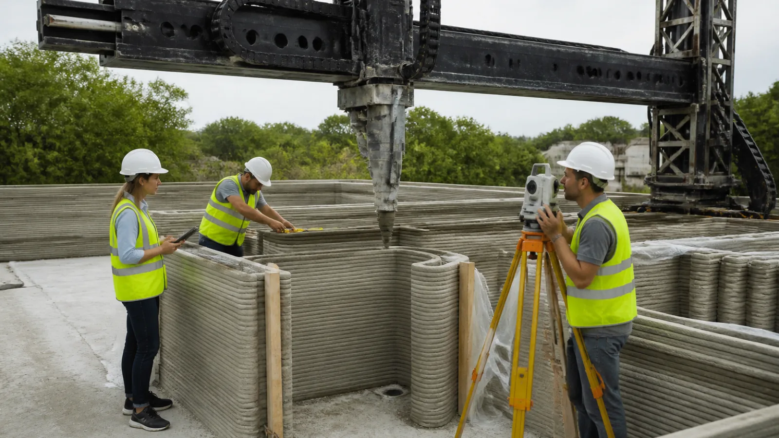
3D printing changes concrete placement from a single, continuously placed pour into a layered process controlled by a digital model, pump, nozzle, material formulation, and print schedule. That change creates quality questions that conventional post-pour inspection alone cannot answer. A wall may look uniform while containing variations in bead geometry, layer timing, interfaces, reinforcement placement, or curing history.
For that reason, ICON’s 3D-printed construction technology and other printing systems must be evaluated through a project-specific process rather than by appearance or general claims about the technology. The objective is to verify that the approved material, equipment, geometry, reinforcement, and workmanship work together as designed.
What 3D Printed Concrete Quality Control Must Prove
Quality assurance and quality control are related but different. Quality assurance, or QA, establishes the system used to achieve consistent work. It covers approved materials, procedures, personnel qualifications, equipment calibration, process planning, inspection plans, and records. Quality control, or QC, is the active checking of that system through measurements, observations, tests, and corrective actions.
In 3D printed concrete construction, the combined program should verify:
- Material consistency, batching accuracy, pumpability, and suitable open time.
- Stable extrusion, bead width and height, layer timing, and print-path accuracy.
- Interlayer bonding, including the effects of time, moisture, pressure, and surface condition.
- Reinforcement continuity, location, anchorage, cover, and compatibility with openings and services.
- Curing, protection, dimensional accuracy, durability, and resistance to early damage.
- Hardened-concrete properties and structural performance where required by the design.
- Traceable evidence that the completed component matches the approved design and process.
Requirements vary by jurisdiction, structural system, materials, printer, project specifications, and approving authority. A process that is suitable for a nonstructural enclosure may not be sufficient for a load-bearing wall, foundation element, retaining structure, or component exposed to severe environmental conditions.
Quality Assurance Before the First Print
Qualifying the Mix and Printing Process
Pre-print qualification should establish that the proposed concrete can be batched, conveyed, extruded, and shaped consistently. Mix trials should examine workability or rheology, which describes how the material flows and resists deformation. The material must be fluid enough to move through the pump and nozzle but stable enough to support subsequent layers without excessive spreading or collapse.
Trials should also address open time: the period during which the material remains suitable for pumping and bonding. Batching controls, aggregate moisture, material temperature, mixing sequence, and water additions can all change consistency. The project team should define how these variables are monitored and what conditions require adjustment, rejection, or a pause.
Qualification should reflect the actual approved equipment and print sequence. A laboratory specimen made with a different nozzle, layer interval, or compaction condition may not represent the behavior of the completed wall. Where interlayer performance is important, test specimens should reproduce the relevant orientation, interface age, surface condition, and printing direction.
Calibrating the Printer, Pump, and Nozzle
Printer calibration is a construction-quality activity, not merely an equipment setup task. The pump output, hose, nozzle dimensions, travel speed, lift height, and control software affect the volume and shape of each deposited bead. Calibration records should identify the equipment, date, settings, material, and person responsible.
Before production, the team should verify continuous extrusion and confirm that the nozzle maintains its intended distance from the previous layer. The pump should not pulse beyond the accepted range, and the nozzle should be free of buildup or partial blockage. Equipment alarms, pressure changes, loss of position, and communications failures should have defined responses so that a small interruption does not become an undocumented defect.
Confirming the Substrate, Digital Model, and Site Conditions
The starting surface must be capable of supporting the printed geometry and transferring loads as designed. Substrate preparation may include cleaning, leveling, moisture conditioning, setting out, and verification of starter reinforcement or connection hardware. The team should confirm that the physical work area matches the coordinate system used by the digital model.
Before printing, review the model for wall thicknesses, openings, corners, changes in direction, embedded items, reinforcement zones, service penetrations, and access for inspection. Printer path verification should confirm that the planned route is achievable without collisions or unsupported movements. Site conditions, including temperature, humidity, wind, direct sun, and precipitation risk, should be recorded against the limits in the qualified procedure.
In-Process Inspection During Concrete Printing
Monitoring Material Consistency and Extrusion
Fresh-material inspection should continue throughout printing rather than stopping after the first batch. The team may monitor batch identity, mixing time, material temperature, moisture conditions, pump pressure, flow behavior, bead dimensions, and visible segregation. The precise tests and acceptance limits should come from the project specification and qualified process.
Operators should look for discontinuous extrusion, tearing, slumping, excessive surface water, aggregate separation, nozzle blockage, irregular bead edges, or changes in color and texture. These observations do not automatically establish a structural failure, but they are signals requiring evaluation. Affected material should be identified by location and time so it can be inspected, repaired, tested, or rejected as appropriate.
Controlling Layer Timing and Interlayer Bonding
Layer bonding is the connection between adjacent printed courses. If the next layer is placed while the previous one remains in a suitable condition, the interface may develop a more effective bond. Excessive delay can create a cold joint, meaning a weaker interface caused by loss of workability or inadequate preparation before the next layer is deposited.
Bond strength and behavior can be affected by the time between layers, surface moisture, drying, temperature, pressure from the new bead, mix design, layer height, and print direction. The interface may also behave differently from the concrete within a bead, creating anisotropic behavior. Anisotropy means that strength or deformation depends on direction.
Inspection should therefore record layer timing and interruptions, particularly around shift changes, equipment maintenance, material replacement, and weather events. If a pause exceeds the qualified interval, the approved procedure may require surface treatment, cleaning, reactivation, a construction joint detail, or engineering review. Testing must reflect the actual approved process; conventional cast-concrete data alone may not establish the performance of printed interfaces.
Checking Geometry, Alignment, and Dimensional Tolerances
3D concrete printing inspection should compare the installed work with the approved digital model and project tolerances. Checks may include bead width and height, wall thickness, openings, plumb, level, alignment, corner locations, surface deviations, and the location of embedded items. The location of reinforcement, sleeves, anchors, and connection hardware should be verified before access is lost.
Laser scanning, photogrammetry, or other measurement tools may help document complex geometry, but they are not universal requirements. Whatever method is selected, records should show the reference points, measurement date, equipment or procedure used, deviations found, and disposition of work outside tolerance. Small differences may be acceptable; cumulative dimensional drift can affect roof connections, door and window installation, cladding, services, and structural load paths.
Reinforcement Strategies for 3D-Printed Concrete
Conventional Bars, Grouted Cores, and Hybrid Reinforcement
There is no single reinforcement method for every printed concrete system. Conventional reinforcing bars may be installed during printing, inserted after selected layers, or placed in formed cavities and grouted cells. Vertical and horizontal bars must maintain their designed locations, continuity, development length, lap arrangements, cover, and connection to adjacent structural elements.
Some systems combine printed shells with grouted cores, mesh, cables, fibers, or post-installed reinforcement. Hybrid systems can be effective when designed as a complete load path, but they also create inspection and sequencing demands. Grout must fill the intended cells or cores without voids, and reinforcement must remain accessible for placement, tying, inspection, and verification.
Fibers and Other Distributed Reinforcement
Fibers can help control cracking or provide distributed reinforcement, depending on their type, dosage, orientation, and the structural design. They should not automatically be treated as a substitute for bars, mesh, tendons, or other primary reinforcement. Printing can influence fiber orientation, and the resulting behavior may differ by direction.
Cables, mesh, mechanically connected reinforcement, and post-installed systems each require their own design assumptions and inspection procedures. The engineer should define what the reinforcement contributes, how continuity is achieved, and how the completed condition will be verified.
Coordination Issues Around Openings, Services, Cover, and Connections
Reinforcement coordination is often most difficult at corners, openings, lintels, wall intersections, foundations, roof connections, and areas with concentrated services. Congestion can interfere with the nozzle path or prevent adequate grout placement. Service penetrations can reduce cover, cut through reinforcement, or create unintended weak zones if they are moved without design review.
Inspection should confirm bar size and spacing where applicable, clear cover, lap and anchorage locations, embedded hardware, and the condition of grouted spaces. Any field change should be documented and approved through the project’s design-control process.
| Reinforcement approach | Typical quality-control concern | Verification focus |
|---|---|---|
| Bars placed during or after printing | Mislocation, inadequate cover, laps, or access | Bar size, spacing, continuity, anchorage, and pre-closure inspection |
| Grouted cores or cells | Incomplete fill, voids, or blocked reinforcement paths | Cell geometry, grout records, consolidation, and targeted verification |
| Mesh, cables, or hybrid systems | Discontinuity, incorrect tension, or coordination with print paths | Layout, connections, anchorage, cover, and approved installation sequence |
| Fibers or distributed reinforcement | Dosage, dispersion, orientation, or unsuitable design assumptions | Batch records, mix controls, process qualification, and design-specific testing |
| Post-installed reinforcement | Incorrect location, drilling damage, or inadequate bond | Design approval, hole preparation, installation records, and proof testing when specified |
Curing and Protection After Printing
Printed geometry does not eliminate ordinary concrete durability and curing concerns. Freshly printed material can lose moisture quickly because of wind, heat, low humidity, direct sun, or a large exposed surface area. Rapid moisture loss can contribute to plastic shrinkage, surface cracking, reduced hydration, or weaker interfaces.
The project should follow a qualified curing procedure that addresses moisture retention, temperature control, protection from wind and heat, and any approved curing compounds, coverings, membranes, misting, or other methods. The selected method must be compatible with subsequent coatings, grouting, bonding, and fire or moisture requirements.
Environmental readings and protection measures should be recorded. The component should also be protected from impact, vibration, freezing, excessive heat, and early loading until it reaches the condition required by the design. Curing duration and acceptance criteria are project-specific and should not be inferred from printed appearance.
Testing and Structural Verification
Fresh-Material and Process Tests
Fresh-material and process testing may include checks of temperature, consistency, workability or rheology, density, batch yield, open time, pump pressure, extrusion stability, and layer dimensions. The relevant combination depends on the material and design. The purpose is to show that the material entering the printer and the material being deposited remain within the qualified process window.
Testing should be coordinated with observations and print logs. A passing material result does not by itself prove that a wall was printed correctly if the nozzle paused, the layer interval changed, or the path deviated. Conversely, a visible irregularity should be evaluated with its location and process history rather than ignored because a separate batch test passed.
Hardened-Concrete and Interface Tests
Hardened-concrete verification may include compressive strength, density, void assessment where relevant, absorption or durability-related tests, and bond or interface testing. Cores or other samples may be required when specified, but sampling locations must be selected carefully so they do not damage critical reinforcement or leave unrepresentative results.
Interface testing should represent the actual layer orientation, age, moisture condition, and print sequence. Structural analysis may be needed to account for directional properties, openings, joints, reinforcement, connections, and observed deviations. Load testing may be considered when required by the design professional or approving authority, but it is not a universal substitute for process qualification and inspection.
Dimensional, Reinforcement, and As-Built Verification
Final verification should confirm the as-built geometry, wall thickness, openings, plumb, connection points, reinforcement, cover, grouted zones, and embedded items. Scans or surveys can provide a useful record of complex surfaces, while targeted openings or other approved methods may verify concealed conditions.
The structural engineer should evaluate whether measured deviations affect load paths, stability, fire protection, water management, finish installation, or service coordination. A component is not ready for permanent incorporation merely because it is complete in the printer’s software; it must satisfy the approved design and inspection requirements.
Documentation and Code Compliance
What the Project Record Should Contain
A traceable project record should connect each printed area to its materials, equipment, process settings, inspections, tests, and approvals. Depending on the project, it may contain:
- Mix designs, batch records, material certificates, lot information, and moisture adjustments.
- Printer, pump, nozzle, and software settings, along with calibration records.
- Environmental readings, layer timing, print logs, equipment alarms, pauses, and restarts.
- Fresh-material observations, dimensional measurements, reinforcement inspections, and curing records.
- Test results, as-built scans or surveys, nonconformance reports, repair records, and engineering dispositions.
- Inspection reports, approvals, sign-offs, and changes to the approved process.
Incomplete records can prevent the team from determining which material or process was used in a specific location. A nonconformance should be documented and evaluated, not concealed. The response may involve repair, additional testing, design review, removal and replacement, or acceptance with documented limitations.
Working With the Engineer and Authority Having Jurisdiction
3D printed construction code compliance is project-specific. A printed wall or component must satisfy the applicable building code, structural design provisions, fire and life-safety requirements, durability provisions, and material or product requirements. Depending on the jurisdiction, the work may require a product evaluation, an alternative-material pathway, a project-specific technical justification, or another form of review.
There is no single global standard that automatically governs every 3D-printed concrete project, and the technology is not universally accepted in every application. The design team should coordinate early with the structural engineer, building official, fire authority where applicable, testing agencies, contractor, and owner. The approving authority should understand the proposed materials, reinforcement strategy, inspection plan, test evidence, limitations, and proposed acceptance criteria before construction begins.
Practical 3D-Printed Concrete Quality-Control Checklist
Use the following as a planning aid and adapt it to the project specifications and approval conditions.
Before printing
- Confirm the approved mix, material sources, batching controls, open time, and qualification results.
- Verify printer, pump, nozzle, path, coordinate system, calibration, alarms, and backup procedures.
- Inspect and prepare the substrate, starter reinforcement, anchors, embeds, and work area.
- Review openings, services, reinforcement zones, tolerances, curing measures, and environmental limits.
- Confirm inspection responsibilities, test methods, hold points, records, and nonconformance procedures.
During printing
- Record batch identity, material condition, temperature, environmental readings, and equipment settings.
- Monitor extrusion continuity, bead geometry, nozzle distance, layer timing, and visible defects.
- Track pauses, interruptions, alarms, material changes, cold-joint risks, and corrective actions.
- Verify reinforcement, embeds, openings, alignment, and critical dimensions before they become inaccessible.
After printing
- Apply the approved curing and protection procedure and document exposure conditions.
- Inspect dimensions, plumb, level, thickness, surface condition, connections, reinforcement, and grouted zones.
- Complete specified fresh, hardened, interface, dimensional, and structural verification.
- Identify, document, and disposition defects, repairs, deviations, and areas requiring additional review.
Before approval or handover
- Compile batch records, calibration data, print logs, environmental records, inspection reports, and test results.
- Submit as-built information, nonconformance dispositions, repair documentation, and engineer sign-offs.
- Confirm that the authority having jurisdiction has received and accepted the required compliance evidence.
- Verify that permanent finishes, services, connections, and later construction will not conceal unresolved defects.
Frequently Asked Questions
How is 3D-printed concrete quality tested?
Testing combines material checks, process monitoring, dimensional inspection, reinforcement verification, curing records, and hardened-concrete or interface tests where required. The methods and acceptance limits should be based on the approved mix, printer, structural system, project specifications, and authority review.
Why is layer bonding important in printed concrete?
Adjacent layers form interfaces that may behave differently from monolithic cast concrete. Time between layers, moisture, surface condition, pressure, mix properties, and print direction can affect bond strength and directional behavior. Testing should reproduce the actual construction process rather than relying only on conventional cast specimens.
How is reinforcement added to 3D-printed concrete?
Depending on the design, reinforcement may include bars installed during or after printing, grouted cores or cells, mesh, cables, fibers, post-installed reinforcement, or a hybrid system. The engineer must define the load path, continuity, cover, anchorage, access, and inspection method for the selected approach.
Does 3D-printed concrete comply with building codes?
Compliance depends on the jurisdiction, application, structural design, materials, evidence, and approval pathway. A printed component must meet applicable structural, fire, life-safety, durability, and material requirements. It should not be assumed that one approval or standard applies universally.
What should be documented on a 3D concrete printing project?
Maintain mix and batch records, material certificates, equipment calibration, environmental readings, print settings, layer timing, interruptions, inspections, tests, curing actions, as-built measurements, nonconformance reports, repairs, engineering decisions, and final approvals. These records establish traceability from the approved process to the permanent work.
Conclusion
Successful 3D printed concrete construction depends on more than a capable printer or a visually consistent wall. Reliable results require a qualified process, project-specific testing, engineered reinforcement, disciplined inspection, controlled curing, and records that explain what was built and how it was verified. Early coordination with the design team and approving authority helps establish realistic requirements before printing begins. With that framework, project teams can evaluate printed components on evidence, manage defects transparently, and determine readiness for incorporation into permanent buildings.