Structural Staircase Design: Calculations, Reinforcement, Analysis Software and Shop Drawings
This practical guide explains how engineers design straight, landing, spiral, curved, cantilever, floating, and precast reinforced concrete staircases. It covers load calculations, bending, shear, deflection, reinforcement detailing, structural analysis software, and the preparation of coordinated shop drawings.
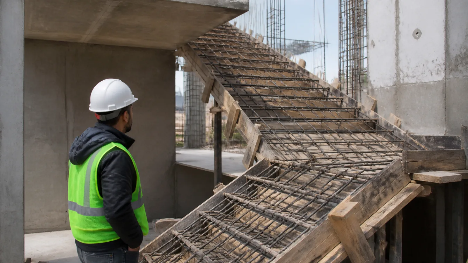
Structural staircase design combines architectural planning, reinforced concrete design, constructability, fire safety, and accurate reinforcement detailing. A staircase must safely carry permanent and imposed loads while remaining comfortable, durable, serviceable, and compatible with the surrounding slabs, beams, walls, landings, and finishes.
This guide presents a practical method for the structural design of reinforced concrete stairs. The numerical example is illustrative rather than a substitute for a project-specific design. Final dimensions, loads, reinforcement, connections, and detailing must be checked by a qualified structural engineer against the governing national code, geotechnical information, fire requirements, and approved architectural drawings.
1. Types of Staircases and Their Structural Behaviour
Straight reinforced concrete staircase
A straight stair is commonly designed as a one-way inclined slab spanning between a lower and an upper support. The main reinforcement generally runs along the slope, with distribution bars across the stair width. It is efficient for apartments, villas, and service stairs because its load path is simple and its reinforcement is easy to fabricate. The supports may be beams, walls, landings, or adjacent floor slabs. Excessive span, vibration, or concentrated reactions at the landings can be limitations.
L-shaped staircase with landing
An L-shaped stair changes direction through an intermediate landing. Each flight may act as a separate one-way slab supported by the landing and floor structure, or the entire stair may be designed as a continuous system. The landing transfers vertical reactions and may also attract torsion where supports are eccentric. L-shaped stairs suit residential and commercial buildings because they fit efficiently into a corner and improve circulation and privacy.
U-shaped staircase
A U-shaped or dog-leg stair contains two parallel flights connected by a landing. The flights usually span between floor slabs and the intermediate landing, with the landing supported by walls, beams, or the stair flights themselves. It is compact and common in apartment cores and high-rise buildings. The designer must check landing reactions, local torsion, construction joints, and the interaction between flights and the surrounding core walls.
Spiral staircase
In a spiral staircase, steps wind around a central post, circular wall, or open void. The structural action can include radial bending, circumferential bending, torsion, punching or local bearing at the central support, and three-dimensional load transfer at the outer edge. Spiral staircase structural design is sensitive to geometry, connection stiffness, tread thickness, crowd loading, vibration, and handrail forces. It is useful where space is restricted, but it is usually less comfortable for primary escape routes and more difficult to detail and construct.
Circular and curved staircase
A circular stair follows a constant-radius plan, while a curved stair may have a changing radius or a free-form alignment. Depending on the support arrangement, the stair can behave as a curved slab, a folded plate, a ribbed system, or a shell. Curved staircase structural analysis must consider torsion, warping, radial forces, circumferential bending, discontinuous supports, and the stiffness of edge beams or walls. These stairs are appropriate for feature spaces, hotels, public buildings, and high-end villas, but require accurate three-dimensional modeling and carefully coordinated formwork.
Cantilever staircase
A cantilever stair has individual treads or a stair slab projecting from a wall or central spine. The fixed support must resist bending moment, shear, torsion, and possible local splitting forces. Cantilever staircase design is architecturally light, but the supporting wall or spine often controls the design. Anchorage length, development of bars, crack control, construction sequence, vibration, and fire protection require particular attention.
Floating staircase
A floating staircase is a visual arrangement in which the treads appear unsupported. The hidden structure may be a reinforced concrete wall, steel spine, concealed stringer, central beam, or cantilever brackets. Floating staircase structural design should not rely on appearance alone: every tread connection must have a defined load path and adequate stiffness. The system is suitable for villas, offices, and commercial interiors, but tolerances, acoustic performance, railing loads, and access for concrete placement can be challenging.
Precast concrete staircase
Precast stairs are manufactured under controlled conditions and lifted into position. They may be single flights, landings, or complete stair units. Design checks include lifting stresses, temporary support, transport, bearing length, connection forces, differential movement, fire resistance, and final-service loads. Precast stairs accelerate construction in apartments and high-rise developments, but the supporting structure and installation tolerances must be coordinated before fabrication.
2. Design Basis and Preliminary Geometry
A reliable design begins with a coordinated architectural plan and section. Confirm the floor-to-floor height, available stairwell length, stair width, headroom, riser and going dimensions, landing sizes, support locations, finishes, balustrades, openings, and fire-escape requirements. The geometry should be checked for comfort before structural sizing.
- Floor-to-floor height: 3.20 m.
- Stair width: 1.20 m.
- Concrete: C30/37.
- Reinforcement: B500B.
- Preliminary waist thickness: 150 to 200 mm.
- Nominal cover: 25 mm, subject to exposure, fire, durability, and code requirements.
For an illustrative straight flight, select 20 risers at 160 mm. Divide the stair into two flights of 10 risers with an intermediate landing if the architectural arrangement is U-shaped. For a single straight flight example, use 20 risers and 19 goings at 280 mm, giving a horizontal going length of 5.32 m. The sloping length is approximately 5.47 m, and the stair angle is about 29.7 degrees. The exact number of treads depends on whether the top floor slab forms the final landing, so the architectural convention must be confirmed before design.
The waist slab thickness is measured perpendicular to the inclined soffit. A preliminary 175 mm waist is adopted for the example. The final thickness is governed by span, reactions, deflection, fire resistance, cover, reinforcement congestion, and the selected design code.
3. Step-by-Step Staircase Structural Calculations
Step 1: Establish the structural idealisation
For a simply supported straight flight, idealise a one-metre-wide strip of the inclined waist slab as a beam spanning between supports. If the landing and flight are monolithic, a continuous model may reduce positive moments but increase negative moments over supports. Do not use a simply supported model where the actual support is a cantilever, fixed connection, or torsionally flexible landing.
The load may be resolved on a horizontal plan projection or along the inclined slab. The chosen method must be used consistently for self-weight, finishes, and imposed load. Many practical designs use loads per horizontal metre because codes and floor loading information are commonly specified on plan area.
Step 2: Calculate the staircase loads
For a 175 mm waist slab, using an illustrative concrete unit weight of 25 kN/m3, the waist self-weight measured on plan is approximately:
gwaist = 25 × 0.175 / cos 29.7° = 5.05 kN/m2
The inclined steps also contribute dead load. If the steps are cast integrally and have an average triangular or wedge thickness of 80 mm over the horizontal projection, their approximate load is:
gsteps = 25 × 0.080 = 2.00 kN/m2
Add finishes, screed, waterproofing, ceiling services, and partitions where applicable. For example, adopt 1.00 kN/m2 for finishes and 0.25 kN/m2 for services. The resulting characteristic permanent action is approximately 8.30 kN/m2.
Adopt an illustrative imposed load of 3.00 kN/m2 for a residential stair, subject to the occupancy category and governing code. The characteristic total load is therefore:
gk + qk = 8.30 + 3.00 = 11.30 kN/m2
For a one-metre-wide design strip, the numerical value is 11.30 kN/m. Include line loads from handrails, parapets, partitions, or edge beams separately. Concentrated loads may be important for public stairs, maintenance access, and balustrade posts.
Step 3: Apply the design load combination
Use the load factors and combinations required by the project code. As an illustration under a common Eurocode-style ultimate combination, take 1.35Gk + 1.50Qk:
wEd = 1.35(8.30) + 1.50(3.00) = 15.71 kN/m
Serviceability combinations are also required for deflection and cracking. Do not apply ultimate factors to serviceability checks, and do not omit accidental, seismic, wind, or construction-stage actions where they are relevant.
Step 4: Perform the staircase bending moment calculation
For a simply supported span of 5.47 m under a uniformly distributed design load of 15.71 kN/m:
MEd = wL2/8 = 15.71 × 5.472/8 = 58.8 kNm per metre width
This is an illustrative idealisation. A continuous stair, landing support, or frame model will produce different positive and negative moments. For inclined slabs, check whether the selected span and loading convention require a horizontal or sloping projection adjustment. Also consider torsion at landings and edge restraints.
Step 5: Perform the staircase shear force calculation
For the same simple-span model:
VEd = wL/2 = 15.71 × 5.47/2 = 42.9 kN per metre width
Check shear near the face of each support rather than only at the theoretical centreline. The effective depth, concrete strength, longitudinal reinforcement ratio, support width, openings, and local load concentrations affect the resistance. In many ordinary stair slabs, flexure governs, but shear must still be formally verified.
Step 6: Calculate the required flexural reinforcement
Assume an effective depth of approximately 140 mm after allowing for cover and bar diameter. With B500B reinforcement, take an illustrative design steel strength of approximately 435 MPa under an appropriate partial factor. A simplified lever arm of 0.9d gives:
As,req = MEd / (0.9d fyd)
As,req = 58.8 × 10⁶ / (0.9 × 140 × 435) ≈ 1,075 mm2/m
A preliminary selection could be 12 mm bars at 100 mm centres, providing approximately 1,131 mm2/m. The final selection must be checked for minimum reinforcement, maximum spacing, anchorage, crack width, bar diameter, construction tolerances, and the actual design moment envelope. If the span, loads, or continuity differ, this reinforcement is not automatically valid.
Step 7: Check minimum, distribution, and support reinforcement
Provide transverse distribution reinforcement perpendicular to the main bars to control cracking and distribute local loads. At the top of a continuous flight or landing, provide negative-moment reinforcement over supports. Extend it sufficiently beyond the critical section with the required anchorage or lap length. Provide local top bars at landings, around openings, and near edges where restraint can cause cracking.
Minimum reinforcement is determined from the relevant code and the concrete tensile strength, section dimensions, steel properties, and crack-control requirements. Bar spacing should allow proper concrete placement and vibration. Reinforcement should be arranged in one or more layers without reducing the effective depth assumed in calculation.
Step 8: Perform the staircase deflection calculation
Deflection may be checked using span-to-effective-depth rules, a calculated cracked-section analysis, or a finite-element serviceability analysis. Consider self-weight, finishes, sustained imposed load, creep, shrinkage, cracking, support flexibility, and the actual stair geometry. A 175 mm waist may be satisfactory for the illustrative span, but this cannot be assumed without checking the code limits and the final reinforcement.
For long, slender, cantilevered, curved, or lightly supported stairs, vibration and perceptible movement can govern before conventional deflection limits are exceeded. Review the natural frequency and walking response where the stair is in a public, commercial, or high-traffic building.
Step 9: Check bearing, anchorage, torsion, and robustness
Verify the bearing length and local compressive stress at landings and supports. Check development length, laps, hooks, couplers, starter bars, and the transfer of forces into beams or walls. Where a landing is supported on one side or a curved flight has eccentric reactions, design for torsion and provide closed links, transverse bars, or edge reinforcement as required.
Review accidental load paths and robustness requirements. Stairs can act as access and escape elements, but they should not be assumed to provide building stability unless they have been intentionally designed and connected as part of the lateral system.
4. Design Considerations for Spiral and Curved Stairs
Spiral staircase reinforcement cannot be detailed by simply placing straight bars along the visible tread direction. First define the central support, outer support, radius, rise per turn, tread geometry, slab or tread thickness, and connection method. Then identify radial bending, circumferential bending, torsion, shear, local bearing, and vibration actions.
A three-dimensional shell or solid model is often appropriate for a circular or curved stair. Use realistic supports and connection stiffness, but avoid interpreting stress peaks at idealised point restraints as directly designable reinforcement demands. Review averaged forces over rational design strips and supplement the model with hand checks for equilibrium and load transfer.
For a stair supported at a central column, check the column connection for punching and torsion. For a stair supported along an inner wall, provide adequate anchorage and confinement. For a free outer edge, consider a concealed ring beam or edge stiffener. Spiral staircase reinforcement should follow the principal tensile force paths, with additional circumferential and local reinforcement at supports and openings.
For curved staircases, a constant-width curved slab may develop significant twisting because the inner and outer edges travel different distances. Curved staircase structural analysis should therefore include warping restraint, edge stiffness, differential deflection, and construction-stage stability. Reinforcement drawings should show bar radii, offsets, bending tolerances, lap positions, and whether bars are radial, circumferential, orthogonal, or fabricated as bespoke shapes.
5. Cantilever and Floating Staircase Design
Cantilever staircase design begins at the fixed support, not at the visible tread. Determine the dead, live, railing, impact, and accidental loads at each tread or along the slab. Calculate the root moment, shear, torsion, crack width, and deflection. The wall, spine, or beam must be designed for the combined forces, and the anchorage must extend into a sufficiently reinforced structural element.
For a single cantilever tread carrying a factored point load P at a projection a, the basic root moment is P a, before adding self-weight and other actions. A repeated series of treads may create significant torsion and local wall forces. Check construction sequence because an unbalanced cantilever may be unstable before the concrete, finishes, and handrail are complete.
Floating stairs require close coordination between architectural finishes and hidden reinforcement. Provide a clear detail for bearing plates, embedded steel, starter bars, sleeves, waterproofing, fire protection, acoustic isolation, and tolerances. Never conceal a structural connection without showing how it is inspected, installed, and protected.
6. Staircase Reinforcement Detailing
Good staircase reinforcement detailing converts calculations into reinforcement that can be placed correctly on site. A typical reinforced concrete stair slab drawing should identify:
- Main longitudinal bars at the bottom of simply supported flights or at the tension face indicated by analysis.
- Top support bars over landings and continuous supports.
- Transverse distribution bars across the stair width.
- Landing reinforcement in both directions where required.
- Edge bars, trimming bars, anchorage bars, and local reinforcement around openings.
- Starter bars, dowels, couplers, laps, hooks, bends, and development lengths.
- Concrete cover, bar marks, spacing, levels, construction joints, and pour sequence.
The reinforcement arrangement must respect the actual inclined geometry. Show bar levels perpendicular to the waist slab, not merely horizontal lines on plan. Indicate how bars pass through the landing, where they stop, and how they are supported with chairs or spacers. Avoid excessive bar curtailment in regions where anchorage or crack control is required.
7. Staircase Reinforcement Drawings and Shop Drawings
A staircase reinforcement drawing should include plan, longitudinal section, transverse section, landing details, enlarged support details, and a reinforcement schedule. The drawing must make the stair buildable without relying on assumptions from the calculation package.
Staircase shop drawings typically contain:
- Setting-out dimensions, grid references, levels, floor-to-floor height, riser, going, landing, and headroom dimensions.
- Concrete grade, reinforcement grade, cover, pour breaks, construction joints, and finish requirements.
- Bar marks, diameters, spacing, shape codes, cutting lengths, quantities, and installation zones.
- Sections showing the waist, tread profile, landing slab, support, wall interface, and edge conditions.
- Coordination with architectural finishes, handrails, balustrades, embedded items, sleeves, and MEP penetrations.
- Revision status, design responsibility, approval references, and site installation notes.
A staircase bar bending schedule should be generated from the approved reinforcement drawing and checked against the actual geometry. Staircase rebar quantity estimation should include straight bars, bent bars, anchorage extensions, laps, couplers, wastage allowances, and separate landing reinforcement. Quantity software or BIM schedules are useful, but the responsible engineer or detailer must verify bar shapes and lengths manually.
8. Structural Analysis Software for Stairs
Finite-element and building-analysis workflows
Simple straight stairs can often be designed with hand calculations and a beam-strip model. More complex stairs benefit from structural analysis software, provided the model represents the real support and load path.
- Autodesk Robot Structural Analysis staircase: useful for beam, plate, and shell models, load combinations, reactions, and design checks where the stair is part of a broader structural model.
- ETABS staircase modeling: practical for stairs connected to reinforced concrete frames and cores. Model flights and landings with suitable shells or equivalent members, then check diaphragm and support assumptions.
- SAP2000 staircase analysis: useful for irregular, curved, cantilevered, or floating systems requiring three-dimensional frame, shell, or solid elements.
- SAFE staircase design: can assist with slab and shell analysis, reactions, design strips, and reinforcement review, although unusual stair geometry may require supplementary checks.
- Revit structural staircase modeling: valuable for BIM coordination, geometry, reinforcement representation, quantities, and clash detection. Revit is not a replacement for structural analysis or engineering judgement.
- AutoCAD staircase shop drawings: remains useful for precise 2D reinforcement plans, sections, bar marks, dimensions, and fabrication details.
When modeling stairs, define the local axes, shell thickness, offsets, releases, mesh size, support widths, diaphragm assumptions, and load application carefully. Avoid double-counting the self-weight of steps or landings. Compare software reactions with hand-calculated equilibrium, inspect deformed shapes, review moment and shear contours, and investigate singularities at point supports and sharp corners.
For BIM staircase design, coordinate the analytical model with the physical model. The visible tread geometry, structural waist, reinforcement cover, and support connections must all agree. Exporting a model or schedule does not confirm that bars can be bent, transported, placed, lapped, or concreted.
9. Eurocode 2 and ACI 318 Design Considerations
Eurocode 2 staircase design generally requires checks for ultimate limit states, serviceability, durability, anchorage, laps, minimum reinforcement, shear, torsion where relevant, and fire resistance. Nationally determined parameters and the applicable execution standards must also be considered. For reinforced concrete stairs Eurocode projects, coordinate the structural assumptions with EN 1991 actions and the project specification.
ACI 318 staircase design requires appropriate strength and serviceability checks, load combinations, development and splice requirements, minimum reinforcement, detailing, and durability provisions. Stair loading may also be influenced by the applicable building and accessibility codes. Do not mix Eurocode material factors, load combinations, detailing rules, and ACI provisions in one calculation without a clearly justified design basis.
The selected code should be stated on the drawings and calculation cover sheet. Include the concrete and reinforcement properties, exposure class, fire rating, design life, load categories, analysis assumptions, and any project-specific departures.
10. Common Design and Detailing Errors
- Using the horizontal going as the structural span without checking the inclined geometry and support locations.
- Ignoring the self-weight of the steps, finishes, landings, handrails, or edge beams.
- Providing only bottom reinforcement and omitting top support bars in a continuous stair.
- Failing to check torsion in curved, spiral, eccentric, or one-sided landing systems.
- Terminating bars at the theoretical support without sufficient development length.
- Showing reinforcement that clashes with stair nosings, waterproofing, sleeves, or balustrade anchors.
- Relying on software output without checking equilibrium, reactions, mesh sensitivity, and support idealisation.
- Designing a cantilever tread without checking the wall, spine, anchorage, vibration, and construction sequence.
- Preparing a bar bending schedule before the reinforcement drawing and geometry are approved.
- Failing to coordinate fire cover, concrete placement access, temporary works, and inspection requirements.
11. Practical Design Workflow
A robust workflow is to confirm the architectural geometry, select the structural system, establish material and loading criteria, perform preliminary sizing, calculate actions, design flexure and shear, check deflection and cracking, design supports and connections, and then prepare coordinated reinforcement drawings. Review the model and drawings together before issuing them for construction.
For unusual stairs, obtain an independent review of the structural concept before detailed reinforcement is produced. Curved, spiral, cantilever, floating, and precast stairs often depend more on connection behavior and construction sequence than on the basic slab calculation. A clear calculation note, accurate model, coordinated shop drawing, and practical site detail are all part of safe stairs structural engineering.
Conclusion
Effective reinforced concrete staircase design connects geometry, load calculation, structural analysis, reinforcement design, detailing, and construction. Straight, L-shaped, and U-shaped stairs can often be designed with transparent one-way slab methods, while spiral, circular, curved, cantilever, floating, and precast stairs require more careful three-dimensional analysis and connection design.
The illustrative staircase structural design example demonstrates the essential sequence: define the span and loads, calculate bending moment and shear, select reinforcement, verify deflection and detailing, and communicate the result through complete reinforcement and shop drawings. The final design must always be checked and approved for the specific project, code, materials, exposure, fire rating, and construction method.