Predictive Maintenance for Construction Equipment: Using Mechatronics to Prevent Hydraulic and Drivetrain Failures
Mechatronic monitoring helps construction fleets identify developing hydraulic, drivetrain, engine, and cooling problems before they cause unplanned downtime. This guide explains sensor selection, alert design, operating context, maintenance workflows, and practical implementation limits.
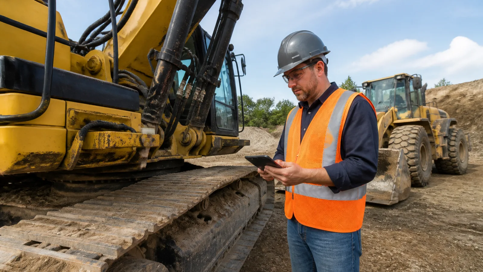
Predictive maintenance for construction equipment uses measured machine condition, operating context, and engineering analysis to identify developing faults before they become disruptive failures. Instead of waiting for a pump, bearing, gear, or final drive to fail, a fleet team watches for changes that indicate deterioration and schedules the right inspection or repair.
Construction machines are difficult to monitor because their loads and environments change constantly. Dust, shock, temperature swings, idle time, attachments, operator behavior, digging resistance, lifting duty, and travel conditions all affect measurements. Well-designed condition monitoring solutions for industrial equipment illustrate the broader principle: useful maintenance decisions require reliable sensing combined with interpretation, not isolated readings. Mechatronics provides the connection between sensors, controllers, machine systems, data analysis, and maintenance action.
What predictive maintenance means for construction equipment
Reactive maintenance begins after a machine stops working or develops an obvious fault. Preventive maintenance uses time, hours, mileage, cycles, or manufacturer service intervals to replace fluids and components before their expected service life ends. Condition-based maintenance uses current measurements, inspections, or diagnostic codes to decide whether service is required. Predictive maintenance adds trend analysis and operating context to estimate whether a developing condition is likely to become a maintenance event.
Prediction does not mean forecasting an exact failure date. A temperature increase may indicate restricted cooling, low oil level, excessive load, or a sensor problem. Confidence improves when the change persists, appears under comparable operating conditions, and is supported by another signal such as reduced efficiency, vibration, pressure instability, or a fault code.
| Maintenance approach | Trigger | Strengths | Limitations |
|---|---|---|---|
| Reactive | Failure or obvious defect | Simple and requires little monitoring | Unplanned downtime, secondary damage, and safety exposure |
| Preventive | Time, hours, cycles, or service interval | Easy to schedule and standardize | May replace usable parts or miss condition changes between services |
| Condition-based | Inspection or measurement outside an accepted condition | Links service to actual machine condition | Requires reliable measurements and competent interpretation |
| Predictive | Trend, model, and context indicating developing deterioration | Supports earlier planning and more targeted intervention | Needs quality data, workflow discipline, and validation |
The machine systems most suitable for predictive monitoring
Hydraulic systems
Hydraulic circuits are strong candidates for construction equipment condition monitoring because pressure, temperature, flow, and response are closely related to machine performance. Sensors may monitor pump outlet pressure, pilot pressure, return-line temperature, reservoir temperature, flow, valve command, and cylinder position. Controller data can also show commanded versus measured pressure or movement.
Useful warning patterns include rising oil temperature during a familiar duty cycle, pressure instability under a consistent load, longer boom or bucket cycle times, and a growing difference between commanded and actual actuator response. These patterns may point to pump wear, internal leakage, a restricted filter, a relief-valve problem, sticky valve behavior, cooler restriction, low oil level, or contamination-related wear. Hydraulic failure detection is strongest when pressure and temperature trends are interpreted with cycle time, engine speed, attachment, and load.
Drivetrains and final drives
Drivetrain monitoring can combine vibration, rotational speed, torque or load estimates, gear-oil temperature, lubrication condition, wheel or track behavior, and abnormal noise where practical. Accelerometers mounted near bearings, gearboxes, axles, or final drives can identify changes in vibration amplitude and frequency content. Speed and load data help distinguish a real fault from normal vibration during travel over rough ground.
Increasing vibration at a bearing frequency or gear mesh frequency may indicate bearing damage, gear wear, looseness, misalignment, or lubrication problems. Rising oil temperature under comparable travel or climbing conditions can support the diagnosis. Uneven wheel speed, track behavior, or clutch response may indicate differential, clutch, brake, or final-drive issues. Drivetrain failure prediction should lead to a controlled inspection rather than an automatic assumption that a particular component has failed.
Engines, cooling systems, and electrical subsystems
Engine controller data can strengthen maintenance decisions by combining coolant temperature, fuel pressure, oil pressure, engine speed, load, battery voltage, alternator behavior, and exhaust aftertreatment signals. Repeated derate events, slow warm-up, abnormal regeneration behavior, or a widening gap between commanded and measured values may justify inspection.
Cooling performance is especially important because hydraulic, engine, and drivetrain temperatures often interact. A machine that overheats only during travel or lifting may have restricted airflow, a failing fan drive, excessive load, or a developing internal fault. These signals support troubleshooting and maintenance prioritization; they do not replace manufacturer diagnostic procedures.
Sensor and data requirements
Common construction equipment sensors include pressure transducers, temperature probes, accelerometers, oil-quality or particle sensors, speed pickups, position sensors, load pins, flow meters, and controller data interfaces. Embedded machine data is usually economical and already connected to the electronic control system, but it may expose only the measurements selected by the manufacturer. Retrofit sensors can add direct measurements at bearings, hydraulic lines, reservoirs, or gearboxes, although installation, protection, calibration, and power requirements become additional responsibilities.
Placement must reflect the failure mode. A pressure sensor installed far from a valve may not capture a local pressure event. A vibration sensor needs a rigid, repeatable mounting point and suitable orientation. Temperature sensors must account for heat sources, airflow, and response time. Sampling frequency should match the phenomenon: slow temperature trends need less frequent collection than gear-mesh vibration. Calibration, environmental sealing, cable protection, signal filtering, and time synchronization are essential in dust, water, impact, and electromagnetic-noise environments.
One sensor rarely proves a failure. Sensor fusion is valuable because a hydraulic temperature increase paired with longer cycle time is more informative than temperature alone. Similarly, a vibration change supported by rising gear-oil temperature and a matching speed range deserves more attention than a single noisy vibration spike.
| Monitored signal | Likely insight | Common limitation |
|---|---|---|
| Hydraulic pressure | Load response, relief activity, pump or valve behavior | Pressure depends strongly on attachment, load, and test location |
| Temperature | Friction, cooling performance, overload, or restricted flow | Ambient temperature and warm-up state affect the reading |
| Vibration | Bearing, gear, looseness, or imbalance changes | Mounting, shock, speed, and structure-borne noise can distort results |
| Oil quality or particles | Contamination, wear debris, oxidation, or water ingress | Sampling location and fluid replacement history affect interpretation |
| Speed and position | Cycle time, slip, travel behavior, and actuator response | Requires accurate synchronization and valid reference signals |
| Load or torque | Operating severity and drivetrain demand | Many systems estimate rather than directly measure load |
| Controller data | Fault codes, derates, commands, and protective actions | Codes may identify a circuit or condition, not the root cause |
How to set useful alert thresholds
Fixed thresholds use a defined limit, such as a manufacturer temperature, pressure, vibration, or contamination limit. Baseline thresholds compare current behavior with the normal range for that specific machine. Trend-based thresholds look for a sustained rate of change, while model-based alerts compare multiple inputs with expected behavior. Manufacturer limits and machine-specific baselines should take priority over arbitrary universal values.
Context variables must be included. Cold starts, heavy digging, lifting, travel, idling, ambient temperature, attachments, terrain, and operator behavior can all change a reading without indicating deterioration. Data should be segmented by operating mode where possible. A hydraulic temperature threshold for continuous lifting should not be applied unchanged during idling, and a drivetrain vibration limit during smooth travel may not be appropriate on rough ground.
Use different alert levels: an informational alert records a change for review; an inspection alert requests a planned check; a scheduled-maintenance alert supports parts and labor planning; and a critical alert requires prompt action under the applicable safety and manufacturer procedures. Persistence windows prevent a single spike from creating unnecessary work. Hysteresis prevents an alert from repeatedly switching on and off around a limit.
False positives waste technician time, while missed detections create risk. Confirmation using multiple signals, repeated observations, and operator or technician feedback helps balance both problems. Thresholds should be reviewed after known repairs, sensor replacement, attachment changes, and major machine configuration changes.
Common failure patterns and what they can indicate
| Symptom or data pattern | Possible cause | Recommended verification | Maintenance response |
|---|---|---|---|
| Rising hydraulic oil temperature with declining cycle performance | Internal leakage, restricted cooler or filter, pump wear, low oil, or overload | Check oil level and condition, filter restriction, pressure, flow, cooler airflow, and cycle times | Schedule diagnosis; correct the confirmed restriction, leakage, cooling problem, or worn component |
| Pressure ripple or unstable pressure under a consistent load | Pump wear, air ingress, valve instability, relief-valve issue, or contamination | Repeat a controlled test and inspect suction circuit, filters, valves, and fluid condition | Plan component inspection or repair based on test results |
| Increasing vibration at a drivetrain bearing or gear mesh frequency | Bearing damage, gear wear, looseness, misalignment, or lubrication problem | Confirm speed and load range, inspect mounting, sample oil, and perform detailed vibration analysis | Adjust inspection urgency and plan bearing, gear, or lubrication work if verified |
| Rising metal particles or oil contamination indicators | Wear, water ingress, dirt entry, oxidation, or incorrect fluid | Use a controlled fluid sample, inspect seals and breathers, and compare with service history | Identify the source, correct contamination, and replace or repair affected components as required |
| Repeated overheating during travel or climbing | Excessive drivetrain load, brake drag, cooling restriction, low lubricant, or final-drive wear | Compare load, speed, terrain, temperatures, oil level, and cooling performance | Restrict use if necessary and perform a focused drivetrain and cooling inspection |
| Controller fault codes combined with abnormal physical measurements | Actual component deterioration, wiring or sensor fault, or control-system issue | Follow the manufacturer diagnostic tree and compare commanded with measured values | Repair the confirmed root cause and verify operation before returning the machine to service |
These patterns identify conditions for inspection; they do not replace qualified diagnosis, safe testing, or manufacturer procedures. A fault code alone is not proof of a failed component, and a normal reading does not eliminate every possible failure mode.
Turning an alert into a maintenance workflow
A practical workflow begins with data capture and validation. The system should associate each observation with the machine ID, hour meter, operating mode, attachment, location, ambient conditions where relevant, and recent maintenance. The alert is then reviewed by the responsible person, who confirms whether the data is credible and whether the issue requires immediate control, inspection, or planned work.
Useful alerts reach the right person with severity, evidence, operating context, and a recommended next step. A work order can include the trend, photographs, diagnostic codes, test procedure, parts availability, and safety requirements. The technician records inspection findings, measurements, replaced components, and the final cause. This creates feedback for threshold improvement and helps distinguish a true detection from a sensor problem or false alarm.
Integration with fleet-management and telematics platforms can provide machine location, hours, utilization, and fault history. A CMMS can convert approved alerts into work orders, reserve parts, assign labor, and preserve service records. Parts planning is more effective when a developing issue is connected to a known component and lead time, but procurement should still follow technical confirmation rather than an unverified alert.
A practical implementation plan for contractors and fleet managers
Start with a high-consequence asset or failure mode
Prioritize a machine where downtime, safety exposure, repair cost, production impact, or parts lead time justifies monitoring. Examples may include a heavily utilized excavator hydraulic pump, a loader final drive, or a crane duty system with a critical lifting-related consequence. Start with one failure mode that can be described, measured, and verified.
Establish a reliable baseline
Collect clean data across normal operating modes, ambient conditions, attachments, and maintenance states. Record known service events and avoid treating data from a machine with a damaged sensor or unresolved fault as normal. Baselines should reflect the individual machine and its actual work rather than an assumed fleet average.
Pilot before scaling
Define measurable objectives such as earlier inspection, fewer unplanned stoppages, improved parts planning, or better visibility of recurring faults. Do not assume a pilot will produce savings or earlier warnings until the data and workflow demonstrate it. Compare alert quality, technician effort, response time, and confirmed findings.
Build ownership and response procedures
Assign responsibility for reviewing alerts, escalating critical conditions, contacting the operator, creating work orders, and closing the feedback loop. Define what can continue operating, what requires inspection at the next shift, and what requires controlled shutdown under manufacturer and site procedures.
Expand selectively
Scale only after validating data quality, alert usefulness, technician adoption, connectivity, and lifecycle cost. Different machine families may need different sensors, baselines, and operating-mode logic. A larger deployment is not automatically a better program if the organization cannot respond consistently.
Limitations, risks, and safety considerations
Predictive systems are limited by sparse failure data, changing machine configurations, damaged sensors, poor connectivity, inconsistent maintenance records, and model drift. A new attachment, software update, rebuilt component, or different lubricant can change the normal signal. Remote sites may produce gaps in data, and a model trained on one machine family may not transfer safely to another.
Monitoring must never override safety interlocks, inspection requirements, load charts, lockout/tagout procedures, or manufacturer instructions. A machine can be unsafe even when monitored values appear normal, and a critical warning should be managed through established site controls. Connected equipment also requires basic cybersecurity practices, including controlled user access, secure credentials, software updates, network separation where appropriate, and clear authority for remote commands.
Predictive maintenance complements routine inspections and preventive service. It cannot reliably detect every failure mode, eliminate wear, or replace fluid changes, lubrication, torque checks, structural inspection, operator reporting, or scheduled component replacement where required.
Predictive maintenance checklist
- Select an asset and failure mode with a clear operational or safety consequence.
- Define the hydraulic, drivetrain, engine, cooling, or electrical measurements needed.
- Confirm sensor placement, environmental protection, calibration, sampling, and time synchronization.
- Collect baseline data across normal loads, attachments, temperatures, and operating modes.
- Use manufacturer limits and machine-specific trends before generic thresholds.
- Separate informational, inspection, scheduled-maintenance, and critical alerts.
- Assign alert ownership, escalation rules, and safe operating controls.
- Connect approved alerts to fleet systems, telematics, CMMS, parts planning, and technician records.
- Record confirmed failures, false alarms, sensor faults, repairs, and inspection findings.
- Review data quality, alert performance, response time, and lifecycle cost at a defined cadence.
Frequently asked questions
What is predictive maintenance for construction equipment?
It is a maintenance approach that uses sensor readings, controller data, operating context, and trend analysis to identify developing equipment deterioration and plan an inspection or repair before a disruptive failure. It estimates changing risk rather than guaranteeing an exact failure date.
Which sensors are most useful for hydraulic equipment?
Pressure, hydraulic oil temperature, return-line temperature, flow, position, cycle-time, and controller data are commonly useful. Oil-quality or particle monitoring can add evidence of contamination and wear. The best combination depends on the circuit, failure mode, machine design, and available test points.
Can telematics predict hydraulic or drivetrain failure?
Telematics can provide valuable hours, load, temperature, fault-code, speed, and utilization data, and it may support hydraulic or drivetrain predictions. However, telematics alone may not include the pressure, flow, vibration, or oil-quality measurements needed for confident diagnosis. Retrofit sensing and technician verification may be necessary.
How are alert thresholds established?
Start with manufacturer limits, then establish a machine-specific baseline across valid operating modes. Add persistence windows, hysteresis, trend rules, and multiple-signal confirmation. Thresholds should be reviewed after repairs, configuration changes, sensor replacement, and confirmed false alarms.
Is predictive maintenance worthwhile for a small construction fleet?
It can be worthwhile when applied selectively to a high-consequence machine or expensive failure mode. A small fleet does not need a complex system to begin. A focused pilot using existing controller data, inspections, oil analysis, or a limited number of retrofit sensors may provide useful evidence before broader investment.
Does predictive maintenance replace scheduled servicing?
No. Scheduled servicing, safety inspections, lubrication, fluid changes, statutory checks, and manufacturer procedures remain necessary. Predictive monitoring adds condition information so teams can prioritize work, investigate emerging problems, and plan repairs more effectively.
Conclusion
Effective predictive maintenance for construction equipment depends on more than installing sensors. The value comes from connecting reliable measurements with engineering interpretation, operating context, qualified inspection, and a clearly assigned maintenance response. Hydraulic pressure and temperature, drivetrain vibration and lubrication condition, controller data, and performance trends can reveal useful changes when they are collected and interpreted together.
The strongest programs begin with a specific failure mode, a reliable baseline, practical alert thresholds, and a workflow that turns evidence into safe action. Used this way, mechatronics in construction equipment complements preventive service and routine inspection while helping fleet teams make better decisions about when to inspect, repair, schedule, or continue monitoring a machine.