Commercial Kitchen Exhaust Design: Hood Sizing, Make-Up Air, Fire Safety, and Commissioning
A practical guide to designing, coordinating, testing, and commissioning commercial kitchen exhaust systems for capture performance, safety, comfort, and reliable operation.
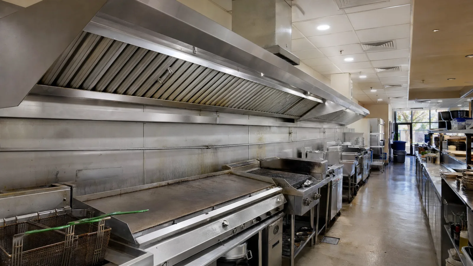
Commercial kitchen exhaust design is not simply a matter of selecting a fan. It is a coordinated MEP, architectural, fire protection, equipment, controls, and operations decision. The system must capture grease-laden vapors, smoke, heat, moisture, and combustion byproducts while maintaining workable pressure, acceptable comfort, manageable noise, and safe equipment operation. Early coordination with the kitchen equipment supplier and providers of commercial kitchen ventilation systems can prevent conflicts between hood geometry, exhaust airflow, make-up air, duct routing, and controls.
Poor planning can result in smoke escaping into the room, grease deposits outside the hood, difficult-to-open doors, odor migration, excessive energy use, nuisance noise, failed inspections, or inaccessible ductwork that is costly to clean. The final design must be coordinated with the adopted building, mechanical, fuel-gas, fire, health, energy, and electrical requirements, the equipment manufacturer, and the authority having jurisdiction.
Key Takeaways
- Begin with the actual cooking equipment, process, duty, operating schedule, and hood listing—not a generic airflow rule.
- Make-up air and pressure relationships are part of capture performance, not a separate late-stage HVAC decision.
- Grease ducts, fans, fire suppression, penetrations, controls, and roof interfaces require coordinated drawings and specifications.
- Testing should measure exhaust, replacement air, pressure, controls, and capture under representative operating conditions.
- Commissioning is incomplete until operators receive usable documentation, maintenance instructions, and training.
What Commercial Kitchen Exhaust Design Must Accomplish
A commercial exhaust system creates a controlled path from the cooking process to the exterior. A hood captures contaminants at their source; the duct conveys them; and the exhaust fan discharges them away from occupied areas and air intakes. The system also has to work with replacement air so that the kitchen does not become excessively negative or positive relative to adjacent spaces.
Source capture is different from general ventilation. A hood is intended to capture a concentrated plume near the equipment. General ventilation dilutes residual heat, odors, and contaminants in the room. Comfort conditioning controls temperature and humidity. A well-conditioned kitchen can still fail if air movement from diffusers, doors, fans, or nearby equipment disrupts the hood plume.
Cooking duty, hood dimensions, mounting height, equipment arrangement, surrounding air movement, operating schedule, and building pressure all influence performance. The design objective is therefore not maximum airflow. It is reliable capture and containment with the least airflow that satisfies the applicable requirements and the listed performance of the hood.
Start With the Cooking Equipment and Hood Type
Type I hoods for grease and smoke
Type I exhaust hoods are typically used over equipment that produces grease-laden vapors or smoke, including fryers, griddles, ranges, charbroilers, woks, and similar appliances. They generally include filters or other listed grease-removal components, grease collection features, cleanable surfaces, and access for inspection and maintenance.
The hood, grease duct, exhaust fan, cooking appliances, and automatic fire-extinguishing system must be treated as one coordinated assembly. Clearances to combustibles, access panels, duct construction, enclosure requirements, and fire suppression interfaces are governed by the adopted requirements and listed equipment. The final equipment lineup must be available before nozzles, detection elements, and interlocks are finalized.
Type II hoods for heat and moisture
Type II hoods are commonly used for equipment producing heat, steam, or moisture without grease-laden vapors, such as some dishwashers, ovens, and steam-producing appliances. The correct classification depends on the actual cooking process, appliance characteristics, manufacturer information, and applicable requirements. An appliance should not be classified solely by its name or location in the kitchen.
Capture-and-containment considerations
Hood overhang, end panels, side skirts, ceiling height, equipment alignment, and the relationship between the hood and the cooking surface all affect capture. Pass-through openings, service counters, adjacent traffic, doors, and shelving can create turbulence or allow the plume to escape. Supply diffusers should not discharge air directly across the hood face.
Airflow cannot fully compensate for poor geometry. A nominally high exhaust rate may still fail when a hood is mounted too high, equipment projects beyond its capture area, or cross-drafts carry smoke into the dining room. The design team should review the complete equipment elevation and nearby air paths, not just the hood schedule.
How to Approach Hood Sizing and Exhaust Airflow
Exhaust airflow should be based on hood type, dimensions, cooking duty, listed performance, mounting conditions, equipment lineup, replacement-air strategy, and the adopted standard or code. There is no universal airflow-per-foot value that applies to every kitchen. Manufacturer data and the requirements governing the project should control the final selection.
Useful design inputs include hood length and depth, mounting height, equipment duty classification, indoor or outdoor location, end-panel configuration, ceiling conditions, kitchen operating schedule, and whether the hood is part of a listed demand-ventilation system. The mechanical schedule, kitchen equipment schedule, hood submittal, fan schedule, controls narrative, and fire protection drawings should use the same airflow and equipment identifiers.
Oversizing can increase fan energy, noise, drafts, heating and cooling loads, and negative pressure. It may also make it harder to maintain stable pressure when the kitchen is lightly loaded. Undersizing can produce visible smoke, grease deposits outside the hood, odor complaints, poor comfort, and failed capture tests. Any proposed reduction in airflow should be supported by the applicable listing, design method, or approved engineering basis.
Make-Up Air and Building Pressure
Exhausted air must be replaced, but make-up air does not necessarily have to equal exhaust airflow through one dedicated unit. Replacement can come from transfer air, dedicated tempered outdoor air, supply plenums, or coordinated HVAC air. The system-level objective is to replace the exhausted volume while maintaining acceptable pressure and preserving hood capture.
Dedicated make-up-air units can provide known outdoor-air volume, filtration, heating, cooling where designed, freeze protection, and independent controls. Transfer air can reduce equipment and operating costs when adjacent spaces are suitable sources, but it depends on door undercuts, grilles, pressure paths, and the operation of neighboring systems. Mixed HVAC replacement air can be effective, but only when the design demonstrates that comfort air, outdoor air, and pressure control remain adequate in all relevant modes.
| Approach | Strengths | Risks | Coordination needs |
|---|---|---|---|
| Transfer air | Uses air from adjacent spaces and may reduce dedicated equipment. | Can create pressure loss, noise, odor transfer, or inadequate flow when doors and grilles are obstructed. | Coordinate pressure paths, door operation, fire and smoke separation, grilles, and adjacent HVAC operation. |
| Dedicated tempered make-up air | Provides a more predictable outdoor-air source with controllable temperature and filtration. | Adds first cost, maintenance, energy use, freeze protection requirements, and equipment space. | Coordinate unit capacity, duct routing, controls, condensate, filtration, intake location, and seasonal sequences. |
| Mixed HVAC replacement air | Can use existing air-distribution infrastructure and integrate with building controls. | Comfort supply may create cross-drafts or fail to provide adequate replacement air during different operating modes. | Coordinate schedules, minimum outdoor air, diffuser placement, pressure sensors, and kitchen operating modes. |
Excessive negative pressure can cause difficult door operation, backdrafting, combustion-air problems, poor hood capture, and odor migration from drains or adjacent rooms. Excessive positive pressure can push contaminants out of the kitchen and into dining areas or neighboring spaces. Heating, cooling, filtration, freeze protection, and seasonal control sequences should be evaluated rather than assuming that untreated outdoor air is acceptable.
Grease Duct Routing, Exhaust Fans, and Roof Coordination
Grease ducts require construction, joints, access, clearances, supports, slopes or drainage provisions where applicable, and fire-rated penetrations that comply with the adopted requirements and the listed system. Concealed sections should remain inspectable and cleanable. Long, indirect routes increase pressure loss and create more opportunities for inaccessible deposits, conflicts, and enclosure problems.
The kitchen exhaust fan must be selected for the required airflow and total system resistance, including hood, filters, duct, fittings, discharge, and any specialty equipment. Review fan rotation, service access, weather exposure, vibration isolation, belt or direct-drive arrangements, roof curbs, structural support, and roof warranty requirements. The discharge should be located to limit re-entrainment into outdoor-air intakes, operable windows, occupied areas, and neighboring properties, subject to project-specific requirements.
Roof coordination should include other exhaust systems, refrigeration equipment, plumbing vents, electrical equipment, access paths, fall protection, and future maintenance space. Exhaust discharge can also affect rooftop air quality and equipment corrosion. The roof plan should show the complete arrangement rather than treating the kitchen fan as an isolated penetration.
Fire Safety and Interdisciplinary Coordination
Commercial kitchen fire safety depends on coordination among the Type I hood, grease duct, fan, cooking appliances, automatic fire-extinguishing system, fuel or electrical shutoffs, alarm interfaces, and emergency procedures. Listed assemblies, clearances to combustibles, access panels, inspection points, and required interlocks should be identified in the design documents without assuming that one discipline will fill in the gaps later.
Fire suppression nozzles and detection elements must match the final appliance arrangement. Changes to fryer size, cooking battery, shelving, or hood configuration can require changes to the suppression design and controls. Treating the fire system as a late add-on creates avoidable inspection and commissioning problems.
A practical coordination review should confirm:
- Architectural: hood elevations, ceiling conditions, wall and shaft construction, access, doors, finishes, and adjacent occupancy separation.
- Mechanical: hood airflow, make-up air, duct route, fan selection, pressure relationships, insulation or enclosure, and controls.
- Electrical: disconnects, power supplies, emergency interfaces, equipment schedules, and control wiring.
- Plumbing: gas service, drainage, grease management, condensate, and conflict-free routing.
- Fire protection: suppression coverage, detection, shutoffs, listed components, inspection access, and alarm interfaces.
- Structural: roof curbs, fan supports, duct supports, seismic restraint where applicable, and penetrations.
- Kitchen equipment: final appliance lineup, clearances, duty, access, and manufacturer requirements.
- Controls: start-stop logic, variable-speed operation, alarms, interlocks, pressure control, and failure responses.
Odor, Noise, Energy, and Indoor Environmental Quality
Restaurant odor control begins with effective capture and containment. Discharge location, fan operation, hood cleanliness, filter condition, duct maintenance, and operating practices also influence complaints. Odor-control equipment may be appropriate for some projects, but it should not be used to compensate for poor hood capture or an incorrectly located discharge.
Review fan sound power, duct velocity, vibration, roof transmission, and kitchen background noise. Acoustic treatment must not obstruct grease-duct access, compromise fire-rated construction, or introduce materials unsuitable for the environment. Vibration isolation and flexible connections should be selected without creating grease accumulation points or maintenance hazards.
Variable-speed drives, demand ventilation, scheduling, and controls integration can reduce energy use when properly engineered. Minimum safe operation, capture performance, fire-system interlocks, and cooking equipment sequences must remain effective at reduced speed. Heat recovery requires particular caution because grease contamination, cross-contamination, cleaning access, listing limitations, and maintenance obligations may outweigh its benefits in some applications.
Testing, Balancing, and Commissioning
Pre-functional checks
Before testing, verify that the hood and equipment lineup match the approved documents; filters and grease components are installed; ductwork is complete and accessible; the fan rotates correctly; belts, bearings, or direct-drive components are ready; dampers and sensors are installed; and controls, fire suppression interfaces, alarms, and shutoffs are connected. Confirm that construction debris, temporary coverings, and blocked grilles are removed.
For a related technical perspective, read AI-Assisted Code Checks and Traceable Design Decisions in Engineering: Myths vs. Facts.
Testing and balancing
Testing and balancing should measure exhaust airflow, make-up-air airflow, transfer paths, supply-air quantities, room pressure, and fan operating points. Measurements should be taken under representative operating conditions, including relevant cooking equipment and HVAC modes where safe and permitted. Document instrument locations, conditions, equipment status, and any temporary adjustments.
Functional performance testing
Functional testing should cover start-up and shutdown, normal and emergency sequences, variable-speed control, alarms, fire-system interfaces, fuel or electrical shutoffs, pressure control, seasonal modes, and failure responses. Smoke visualization or another approved capture-and-containment method can help identify cross-drafts and escape paths when performed by qualified personnel under safe conditions.
Closeout documentation
Closeout should include final balancing reports, equipment schedules, control sequences, as-built drawings, inspection records, cleaning access information, preventive-maintenance procedures, filter and belt information, fire-system records, and operator training. Operators should understand normal start-up, shutdown, alarm response, cleaning responsibilities, and the consequences of disabling interlocks.
Common Commercial Kitchen Exhaust Design Mistakes
- Selecting airflow before the cooking equipment lineup and hood geometry are final.
- Treating make-up air as a separate late-stage HVAC decision.
- Discharging exhaust near outdoor-air intakes, operable windows, or neighboring openings.
- Creating cross-drafts with diffusers, doors, transfer grilles, or fans.
- Routing grease ducts without adequate access, support, clearance, or coordinated fire-rated enclosures.
- Omitting controls, alarms, and interlocks from the design documents.
- Balancing the system with incomplete equipment or unrealistic operating conditions.
- Failing to provide a practical operations and maintenance plan.
Commercial Kitchen Exhaust Design Checklist
- Confirm the equipment schedule, cooking processes, duty, operating hours, and final hood classification.
- Document the airflow basis, hood dimensions, mounting conditions, listing data, and applicable requirements.
- Coordinate make-up air, transfer paths, pressure relationships, heating, cooling, filtration, and freeze protection.
- Verify the grease duct route, access, clearances, enclosure, penetrations, supports, and cleaning provisions.
- Coordinate the kitchen exhaust fan, roof curb, discharge, vibration isolation, service access, and structural support.
- Coordinate fire suppression, detection, fuel or electrical shutoffs, alarm interfaces, and emergency sequences.
- Review diffuser placement, acoustics, odor control, variable-speed operation, and energy sequences.
- Plan testing, balancing, capture verification, functional testing, documentation, and operator training before construction is complete.
Frequently Asked Questions
What is the difference between a Type I and Type II commercial hood?
A Type I hood is generally used for grease-laden vapors and smoke from equipment such as fryers, griddles, ranges, broilers, and woks. A Type II hood is generally used for heat and moisture without grease-laden vapors. The actual cooking process, appliance information, and adopted requirements control the classification.
How is commercial kitchen exhaust airflow determined?
Airflow depends on the hood listing or design data, dimensions, cooking duty, mounting conditions, equipment arrangement, surrounding air movement, replacement-air strategy, and applicable requirements. A single universal airflow-per-foot value is not a reliable design method.
Does make-up air have to equal kitchen exhaust airflow?
The entire exhausted volume must be replaced through a coordinated combination of transfer air, dedicated make-up air, and HVAC air. The quantities and distribution should maintain acceptable pressure and capture rather than simply matching exhaust through one unit.
Why can a correctly sized hood still fail to capture smoke?
Cross-drafts, poor overhang, excessive mounting height, equipment changes, supply-air placement, pressure imbalance, pass-through openings, and unusual operating conditions can defeat capture even when the fan airflow appears correct.
What should be included in kitchen exhaust commissioning?
Commissioning should include airflow measurements, pressure checks, controls and interlocks, fire-system coordination, representative operating tests, capture verification, final documentation, maintenance information, and operator training.
Conclusion
Effective commercial kitchen exhaust design begins with the cooking process and succeeds through coordinated hood geometry, air balance, grease duct routing, fire safety, controls, constructability, and commissioning. The most reliable projects establish the equipment lineup early, coordinate replacement air with the complete HVAC system, protect maintenance access, and test the installation under realistic operating conditions. MEP engineers, kitchen consultants, contractors, fire protection teams, and operators should resolve these interfaces before installation rather than relying on field corrections.
Sources
Applicable editions of the International Mechanical Code, International Building Code, International Fuel Gas Code, and International Fire Code; NFPA 96, Standard for Ventilation Control and Fire Protection of Commercial Cooking Operations; ASHRAE Handbook guidance on commercial kitchen ventilation; and the approved manufacturer installation, listing, and maintenance instructions for the selected hood, fan, duct, and fire-extinguishing equipment.