The Complete Guide to Retaining Wall Design: Calculations, Codes, and Drawings
Proper retaining wall design is a complex process crucial for safety and longevity. This comprehensive guide covers everything from geotechnical analysis and lateral earth pressure calculations to stability checks, drainage systems, and structural drawings.
Introduction
A retaining wall is a structure designed and constructed to resist the lateral pressure of soil when there is a desired change in ground elevation that exceeds the soil's angle of repose. In civil engineering and construction, these structures are fundamental for creating usable, level ground on sloped terrain for everything from highways and bridges to commercial developments and residential landscapes. Proper retaining wall design is a complex, multi-disciplinary process critical for ensuring the safety, stability, and longevity of the structure. A failure can be catastrophic, posing a significant risk to property and life.
While many types of retaining walls exist—including traditional gravity, cantilever, and anchored walls—engineers are increasingly utilizing advanced solutions like segmental retaining wall (SRW) systems for their versatility and efficiency. Regardless of the type, the engineering principles remain paramount. This article serves as a comprehensive guide for engineers, detailing the entire design process, from initial soil analysis and pressure calculations to stability analysis, drainage considerations, software utilization, structural drawings, and code compliance.
Foundational Principles: Soil Mechanics and Lateral Earth Pressure
Every successful retaining wall design begins not with concrete or steel, but with a thorough understanding of the soil it must retain. Soil is the primary load-acting element, and its properties dictate the forces the wall must resist. This is the domain of geotechnical engineering and soil mechanics.
The Role of the Geotechnical Report
The cornerstone of any structural retaining wall project is a site-specific geotechnical report. This document, prepared by a geotechnical engineer, provides the essential data needed for accurate design. Key information includes:
- Soil Type and Classification: Identifies the soil as clay, silt, sand, or gravel, which determines its behavior.
- Shear Strength Parameters: This includes the cohesion (c) and the internal angle of friction (φ), which define the soil's ability to resist shear stresses.
- Unit Weight (γ): The weight of the soil per unit volume, which is used to calculate the vertical and lateral pressures.
- Groundwater Levels: The presence of water significantly increases pressure on the wall and must be accounted for.
- Bearing Capacity: The maximum pressure the soil beneath the wall's foundation can safely support without failure.
Designing a significant retaining wall without a geotechnical investigation is a major professional liability. It forces the engineer to rely on assumed values, introducing a high degree of uncertainty and risk into the project.
Calculating Lateral Earth Pressure: Rankine vs. Coulomb Theory
Lateral earth pressure is the horizontal force exerted by the retained soil mass on the wall. This force is not constant and depends on the movement of the wall relative to the soil. We consider three states:
- At-Rest Pressure: Occurs when the wall is completely rigid and does not move.
- Active Pressure: The minimum pressure state, which occurs when the wall moves away from the soil. This is the primary pressure used for design.
- Passive Pressure: The maximum pressure state, which develops when the wall is pushed into the soil. This can be used as a resisting force at the toe of the wall.
Two classical theories are used to calculate these pressures:
- Rankine Theory (1857): Assumes a smooth, vertical wall with no friction between the wall and the soil. It is simpler to apply and suitable for many cantilever and gravity wall designs with a level backfill. The active earth pressure coefficient (Ka) is calculated as: Ka = (1 - sin(φ)) / (1 + sin(φ)).
- Coulomb Theory (1776): A more general method that accounts for wall friction and a sloped backfill. It is more complex but provides a more accurate result for these common conditions.
Surcharge Loads and Their Impact
Surcharge loads are any additional vertical loads applied to the surface of the backfill behind the wall. These loads create additional lateral pressure that must be included in the retaining wall calculations. Common examples include:
- Uniform Surcharge: Caused by distributed loads like a parking lot or building foundation. This adds a uniform rectangular pressure distribution to the wall.
- Point/Line Surcharge: Caused by concentrated loads like a vehicle wheel or a fence post footing. The pressure from these loads dissipates with depth.
Step-by-Step Stability Calculations for Gravity and Cantilever Walls
Once all forces acting on the wall are determined, the design must be checked for stability against three primary modes of failure. These checks ensure the wall will not move or fail as a complete unit.
Checking for Overturning
Overturning is the tendency of the wall to tip or rotate about its forwardmost point, known as the toe. The calculation involves a moment analysis:
- Overturning Moments (Mo): These are generated by the horizontal forces (lateral earth pressure, surcharge pressure) acting to tip the wall over.
- Resisting Moments (Mr): These are generated by the vertical forces (the wall's self-weight, the weight of the soil on the wall's heel) that act to keep the wall stable.
The Factor of Safety (FS) against overturning is calculated as FS = Mr / Mo. A typical required factor of safety is FS ≥ 1.5 to 2.0, depending on the applicable building codes and the criticality of the structure.
Checking for Sliding
Sliding is the tendency of the wall to slide horizontally along its base due to the lateral forces. This check compares the forces pushing the wall to the forces resisting that movement:
- Driving Forces (Fd): The sum of all horizontal forces from earth pressure and surcharges.
- Resisting Forces (Fr): The frictional resistance between the concrete base and the underlying soil, plus any passive pressure developed at the toe of the wall. The frictional force is calculated as the total vertical weight multiplied by the coefficient of friction for the soil.
The Factor of Safety (FS) against sliding is calculated as FS = Fr / Fd. The generally accepted minimum factor of safety is FS ≥ 1.5.
Checking for Bearing Capacity Failure
This check ensures the soil beneath the foundation is strong enough to support the total load imposed by the wall and the retained soil. The calculation involves:
- Determining the total vertical force and the location of its resultant.
- Calculating the soil pressure distribution under the footing. Due to the overturning moment, this pressure is typically trapezoidal, with the maximum pressure at the toe.
- Comparing the maximum bearing pressure (q_max) to the allowable bearing capacity (q_allow) provided in the geotechnical report.
It is also critical to ensure the resultant force falls within the middle third of the footing's base. This prevents uplift at the heel and ensures the entire footing is in compression, which avoids tensile stresses in the soil.
The Critical Role of Drainage in Retaining Wall Design
Uncontrolled water is the single most common cause of retaining wall failures. The buildup of water behind a wall creates hydrostatic pressure, a force that can be significantly greater than the lateral earth pressure alone. An effective drainage system is not an option; it is an essential component of every retaining wall design.
Common Drainage System Components
- Granular Backfill: A zone of clean, free-draining gravel or crushed stone placed directly behind the wall. This material allows water to percolate down to the drainage pipe instead of building up pressure against the wall.
- Weep Holes / Pipe Outlets: Small openings or pipes that pass through the wall's stem at its base. They provide a direct outlet for water collected in the granular backfill to escape.
- Geotextile Filter Fabric: A permeable fabric placed between the granular backfill and the native soil. Its crucial function is to prevent fine soil particles from migrating into and clogging the gravel and drainage pipes, which would render the system useless over time.
Designing Subsurface Drainage
A typical and effective subsurface drainage design includes a vertical 'chimney' drain of granular material against the back of the wall stem, connected to a perforated pipe laid in a gravel trench along the base of the wall. This pipe should be sloped to drain by gravity and must 'daylight' to a safe location away from the wall, such as a storm drain or a lower-elevation area. Additionally, the ground surface above the wall should be graded to direct surface runoff away from the backfill zone.
Leveraging Software for Efficient Retaining Wall Design
While understanding and performing hand calculations are essential for grasping the fundamental principles of retaining wall stability, modern engineering practice relies heavily on specialized software for design and analysis.
Popular Software Tools and Their Applications
Numerous software packages are available to assist engineers in retaining wall design. Common examples include GEO5, RetainPro, and specific modules within larger structural analysis suites like Bentley's STAAD or CSI's SAP2000. These tools can rapidly perform all the required stability checks (overturning, sliding, bearing capacity), analyze complex loading conditions like seismic forces and tiered walls, and even perform the structural design of the concrete and reinforcing steel components of a cantilever wall.
Benefits and Limitations of Design Software
The primary benefits of using software are speed, precision, and the ability to iterate designs quickly to find the most efficient solution. However, engineers must be cautious of the 'garbage in, garbage out' principle. The software's output is only as reliable as the input data, particularly the soil parameters from the geotechnical report. Software is a powerful tool that assists engineering judgment, but it never replaces it. The engineer remains responsible for verifying the reasonableness of the results and understanding the underlying calculations.
Developing Comprehensive Structural Drawings
The final design is communicated to the contractor through a set of clear and detailed structural drawings. These documents are the legal and technical blueprint for construction, leaving no room for ambiguity.
Key Elements of a Retaining Wall Drawing Set
A complete set of drawings for a retaining wall should include:
- Plan View: Shows the wall's location, length, and alignment relative to property lines and other site features.
- Wall Elevation: Shows the wall's profile, including top and bottom elevations and any steps in the footing.
- Typical Sections: Cross-sectional views are the most important part, showing the wall's geometry, footing dimensions, backfill type and limits, drainage system details, and any geogrid reinforcement.
- General Notes: This section lists the design parameters used, such as soil properties, material specifications (e.g., concrete compressive strength f'c, rebar grade), and required factors of safety.
Reinforcement Detailing and Specifications
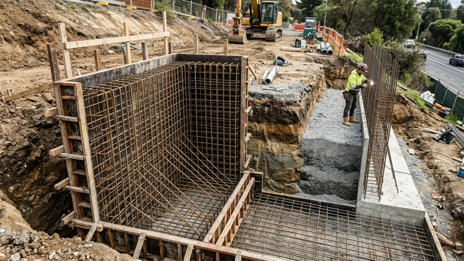
For concrete cantilever walls, the drawings must meticulously detail the reinforcing steel (rebar). This includes specifying the size, spacing, location, and bending shapes of all bars in the stem, heel, and toe. Critical details like required concrete cover (to protect the steel from corrosion), lap splice lengths, and development lengths for bars must be clearly shown to ensure the wall has the required structural capacity.
Navigating Building Codes and Regulations
All retaining wall designs must adhere to the standards and requirements set forth in the governing building codes for the project's location. These codes provide a minimum standard for safety and performance.
Key Provisions in the International Building Code (IBC)
The International Building Code (IBC) is the most widely adopted model code in the United States. IBC Chapter 18, 'Soils and Foundations,' contains the primary provisions for retaining wall design. Key sections address:
- Lateral Soil Loads: Specifies the methods for determining design lateral soil loads.
- Design Load Combinations: Provides the load combinations (e.g., dead load + live load + earth pressure) that must be considered.
- Factors of Safety: Prescribes the minimum required factors of safety against sliding and overturning.
Local Amendments and Jurisdictional Requirements
It is crucial for the design engineer to always check for local amendments to the model building code. Cities, counties, and states often adopt the IBC but add their own more stringent requirements. These amendments are particularly common in areas with unique challenges like high seismic activity, expansive soils, or steep hillsides. The local building department is the final authority on code compliance.
Conclusion
A successful retaining wall design is a synthesis of geotechnical investigation, rigorous engineering calculations, and practical construction considerations. The key pillars—accurate geotechnical data, meticulous stability and structural analysis, a robust drainage system, and clear, comprehensive drawings—are all interconnected. A failure in one area compromises the entire system. By treating the retaining wall as an integrated system where soil, structure, and water management must work in harmony, engineers can ensure the construction of safe, durable, and cost-effective structures that perform their function for decades to come.