The Complete Guide to Swimming Pool Structural Design: Calculations, Codes, and Waterproofing
This authoritative guide covers the essential engineering principles behind in-ground swimming pool structural design, from geotechnical analysis and load calculations to reinforcement detailing and advanced waterproofing strategies.
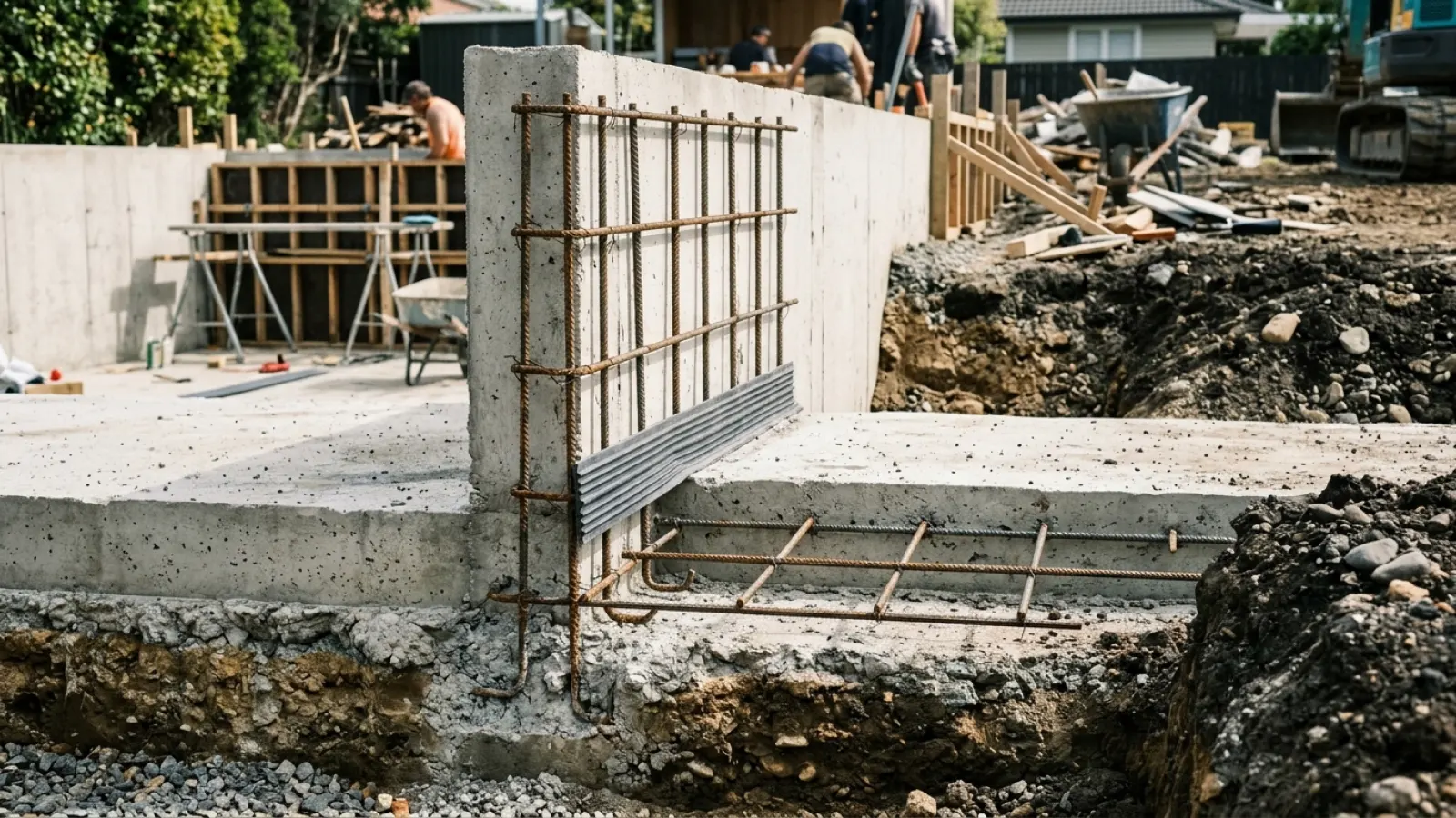
A backyard swimming pool is often seen as a symbol of leisure, but beneath the tranquil water surface lies a complex engineering structure. The successful design of an in-ground reinforced concrete pool goes far beyond aesthetics; it requires a rigorous application of structural principles to manage immense forces and ensure long-term durability. A robust design must account for everything from soil pressure and water weight to material science and code compliance.
This comprehensive guide delves into the critical stages of swimming pool structural design, covering geotechnical assessment, load calculations, reinforcement detailing, software utilization, and waterproofing. Central to achieving a leak-free and durable structure is an effective waterproofing strategy. While traditional membranes offer a surface barrier, modern solutions like crystalline waterproofing admixtures are integrated directly into the concrete mix, creating a permanent, self-sealing barrier that protects the structure from within.
Foundational Principles: Site Assessment and Geotechnical Investigation
Every successful structural design begins not with a drawing, but with an understanding of the ground it will occupy. A thorough geotechnical investigation is a critical roadmap for the engineer, providing essential data that informs every subsequent calculation and decision.
Understanding Soil Properties and Bearing Capacity
The geotechnical report analyzes core samples to identify key soil parameters, including soil type, density, cohesion, and friction angle. This data is used to determine the soil's ultimate bearing capacity—its ability to safely support the weight of the pool structure without excessive settlement. Designing a pool on soil with inadequate bearing capacity without proper ground improvement can lead to cracking, tilting, and catastrophic failure.
Analyzing the Water Table and Its Impact
The report also identifies the depth of the groundwater table. This is a crucial factor, as a high water table can exert significant hydrostatic uplift pressure on the pool's floor slab when the pool is empty. In extreme cases, this upward force can be strong enough to lift the entire pool shell out of the ground. The design must incorporate measures to counteract this force, such as a thicker, heavier slab or a sub-slab drainage system.
Key Structural Loads in Swimming Pool Design
A swimming pool is a dynamic structure subjected to a variety of powerful forces. The structural design must account for all potential load combinations to ensure stability throughout its service life.
Hydrostatic Pressure (Internal Water Load)
When the pool is full, the water exerts outward pressure on the walls and downward pressure on the floor. This hydrostatic pressure increases with depth, creating a triangular load distribution on the walls. The design must ensure the walls and their connection to the slab can safely resist this constant force.
Lateral Earth Pressure (External Soil Load)
The soil surrounding the pool exerts an inward pressure on the walls. The magnitude of this pressure depends on the type of soil, its compaction level, and the presence of groundwater. Engineers analyze this force using principles of soil mechanics, considering at-rest, active, and passive pressure conditions depending on the construction sequence and wall movement.
Surcharge Loads
Additional loads adjacent to the pool must also be considered. These surcharge loads can come from pool decking, planters, nearby building foundations, or even temporary construction equipment. These loads increase the lateral pressure on the pool walls and must be factored into the calculations.
Empty Pool Condition vs. Full Pool Condition
While the full pool condition seems intuitive, it is often the empty pool condition that governs the design. When the pool is drained for maintenance, the internal hydrostatic pressure is removed. The walls must then resist the full inward pressure from the soil and any surcharge loads on their own. Simultaneously, the floor slab must resist the full hydrostatic uplift from groundwater without the counteracting weight of the pool water.
Step-by-Step Structural Calculation and Analysis
With the loads defined, the engineer performs detailed calculations to size the structural elements and specify the required reinforcement.
Calculating Wall Thickness and Floor Slab Design
The pool walls are typically analyzed as retaining walls. Depending on the design, they may be modeled as cantilever walls (fixed at the base) or propped cantilever walls (supported by the slab at the bottom and the deck at the top). The floor slab is designed as a slab-on-grade, accounting for the downward weight of the water and the potential for upward hydrostatic pressure. These analyses determine the required thickness of the concrete to prevent failure in bending and shear.
Reinforcement Design: Sizing and Spacing Rebar
Concrete is strong in compression but weak in tension. Steel reinforcement (rebar) is placed within the concrete to resist the tensile forces caused by bending. Based on the calculated bending moments, engineers determine the required area of steel and specify the rebar size and spacing. Typically, two curtains of rebar (one near each face) are used in pool walls to handle both inward and outward pressures.
A Note on Freeboard and Coping Design
The top edge of the pool, known as the bond beam or freeboard, requires special attention. This section must be designed to support the coping stones or pavers and integrate structurally with the surrounding pool deck, ensuring a stable and durable edge.
Leveraging Structural Design Software
While manual calculations are fundamental, modern structural engineering relies on powerful software to perform complex analyses with high accuracy, especially for freeform or complex pool shapes.
Finite Element Analysis (FEA) with STAAD.Pro or SAP2000
FEA software allows engineers to create a detailed 3D model of the pool shell. The software divides the structure into a mesh of smaller elements, enabling a precise analysis of how stresses, moments, and deflections are distributed under various load combinations. This is invaluable for optimizing reinforcement and verifying the design's safety.
BIM and Detailing with Revit or AutoCAD
Once the analysis is complete, the design is translated into construction documents using CAD or Building Information Modeling (BIM) software. Programs like AutoCAD and Revit are used to create detailed plans, sections, and elevations that clearly communicate every aspect of the structural design to the construction team.
Choosing the Right Software for the Job
For a simple rectangular pool, standardized design charts or simpler analysis methods may suffice. However, for pools with complex geometries, infinity edges, or challenging site conditions, a full FEA is the industry standard for ensuring an accurate and efficient design.
From Analysis to Construction: Structural Drawings and Details
The structural drawings are the final output of the design phase and the primary communication tool for the contractor. Clarity and completeness are paramount.
Key Components of a Structural Drawing Set
A typical drawing set for a swimming pool includes:
- General Notes: Specifies concrete strength, rebar grade, required concrete cover, and other quality control standards.
- Plan Views: Show the pool's dimensions, wall and floor thicknesses, and locations of fittings.
- Sections and Details: Provide cross-section views of the walls and floor, showing reinforcement placement and critical connections.
Reinforcement Detailing and Schedules
Drawings must include precise reinforcement details, showing bar sizes, spacing, lap splice lengths, and special arrangements at corners and openings. A rebar schedule quantifies all the required steel, which is essential for procurement and fabrication.
Waterproofing and Joint Details
The drawings must explicitly detail the waterproofing system. This includes specifying the type and location of waterstops at all construction joints and providing application details for any membranes or integral systems to ensure a fully watertight structure.
Ensuring Longevity: Waterproofing Strategies for Concrete Pools
A pool is designed to hold water, making waterproofing a non-negotiable component of its design. A failure in the waterproofing system can lead to leaks, concrete degradation, and corrosion of the reinforcing steel.
Surface-Applied Membranes (Liquid, Sheet)
These traditional methods involve applying a waterproof layer, such as a liquid-applied polyurethane or a PVC sheet membrane, to the interior surface of the pool. While effective initially, they are susceptible to damage from abrasion, chemicals, and UV exposure, and may require reapplication over time.
Integral Waterproofing Systems (Crystalline Admixtures)
A more advanced approach involves using admixtures that are added directly to the concrete mix. These chemicals react with water and cement particles to form a non-soluble crystalline structure within the concrete's pores and capillaries. This makes the concrete itself the waterproof barrier, providing permanent protection that cannot be punctured and can even self-seal minor shrinkage cracks that may form.
Waterstops for Construction Joints
Construction joints, where two separate concrete pours meet (e.g., between the floor and walls), are inherent weak points for water leakage. Waterstops—strips of PVC, bentonite clay, or other materials—are embedded into the concrete across these joints to create a physical barrier against water migration.
Navigating Building Codes and Standards
Adherence to established building codes is mandatory to ensure public safety and structural adequacy. For reinforced concrete pools, two key documents from the American Concrete Institute (ACI) are paramount.
ACI 318: Building Code Requirements for Structural Concrete
ACI 318 is the foundational code for nearly all structural concrete in the United States. It provides the minimum requirements for material properties, design load combinations, analysis methods, and detailing of reinforcement for general concrete structures.
ACI 350: Code Requirements for Environmental Engineering Concrete Structures
Because pools are water-retaining structures, they often fall under the purview of ACI 350. This code is more stringent than ACI 318, with specific provisions aimed at enhancing durability and water-tightness. Key requirements include increased reinforcement cover to protect against corrosion and stricter limitations on crack widths under service loads.
Local Building Codes and Permit Requirements
Engineers must always consult the governing local building code, which may have amendments to the ACI standards. Local codes also dictate non-structural requirements, such as safety fencing, gate latches, setbacks from property lines, and electrical bonding.
The structural design of a swimming pool is a sophisticated process that demands a deep understanding of geotechnical engineering, structural analysis, material science, and building codes. By systematically addressing each stage—from site investigation to final detailing—engineers can create structures that are not only beautiful but also safe, durable, and watertight for decades to come. It is this meticulous, behind-the-scenes work that transforms a construction project into a lasting asset.
Frequently Asked Questions (FAQ)
Q1: What is the most critical load case for a swimming pool design?
A1: The empty pool condition is often the most critical, especially in areas with a high water table. Without the internal water pressure to counteract external forces, the structure must resist the full lateral earth pressure and potential hydrostatic uplift on the slab.
Q2: How thick should the concrete walls of a swimming pool be?
A2: There is no single answer, as the thickness depends on the pool's depth, soil conditions, and overall design. However, residential concrete pool walls are typically between 8 to 12 inches (200-300 mm) thick, determined by specific structural calculations.
Q3: Why is ACI 350 often referenced for swimming pool design?
A3: ACI 350 is designed for structures that contain liquids, like water treatment tanks. It includes stricter serviceability requirements, such as tighter crack width limitations, to ensure water-tightness and enhance durability, making its principles highly applicable to swimming pools.
Q4: What's the difference between integral and membrane waterproofing for pools?
A4: Membrane waterproofing is a surface-applied barrier that can be damaged or degrade over time. Integral waterproofing, such as a crystalline admixture, becomes part of the concrete itself, providing permanent protection that self-seals minor cracks and cannot be punctured or worn away.