An Engineer's Guide to FRP for Bridge Rehabilitation
This technical guide provides structural and civil engineers with a comprehensive overview of using Fiber-Reinforced Polymer (FRP) systems for bridge rehabilitation. Discover the engineering principles, design considerations, and application processes for carbon fiber wraps and laminates to address common structural deficiencies.
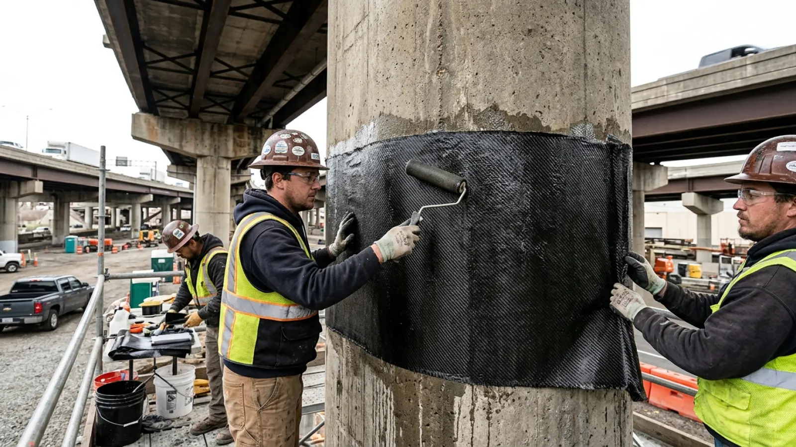
The challenge of aging bridge infrastructure is a critical concern for civil engineers and asset managers worldwide. Traditional repair methods, such as concrete section enlargement or external post-tensioning, often involve significant traffic disruption, heavy equipment, and a substantial increase in structural dead load. In response, Fiber-Reinforced Polymer (FRP) has emerged as a transformative solution, offering a high-strength, lightweight, and durable alternative for extending the life of these vital assets. These advanced composite materials are fundamentally changing how engineers approach structural retrofitting and rehabilitation. This article serves as a technical guide for engineers, detailing the process from identifying bridge deficiencies to the design, application, and long-term performance of FRP strengthening systems.
Identifying Common Bridge Deficiencies Amenable to FRP Strengthening
Before an effective solution can be designed, a thorough diagnosis of the structural problem is essential. FRP systems are highly effective at addressing specific failure modes common in concrete bridges, which typically stem from material degradation, outdated design codes, or increased service loads.
Flexural Deficiencies in Girders and Slabs
A primary function of bridge girders and deck slabs is to resist bending forces, or flexure. Over time, increased legal load limits or the natural degradation of materials, particularly corrosion of internal steel reinforcement, can lead to insufficient flexural capacity. This results in tensile stresses in the concrete exceeding its modulus of rupture. Engineers can identify this deficiency through signs like excessive vertical deflection and the formation of flexural cracks on the tension face of the member, often initiating at the point of maximum bending moment.
Shear Weakness in Beams and Columns
Shear forces act to slice through a structural member. Deficiencies in shear capacity are particularly dangerous because they can lead to a sudden, brittle failure with little warning. This weakness may be present due to original designs that used less stringent shear reinforcement standards, or it can develop from increased load demands that exceed the concrete's capacity and the contribution of internal steel stirrups. Diagonal cracking (shear cracks), typically oriented at approximately 45 degrees, is the most prominent visual indicator of shear distress.
Loss of Confinement and Axial Capacity in Columns
Concrete columns rely on internal steel ties or spirals to confine the concrete core, which enhances their strength and ductility, especially under seismic loading. This confinement creates a triaxial state of stress, preventing lateral expansion of the concrete and delaying failure. This confinement can be compromised by vehicle impact, freeze-thaw cycles, or corrosion of the steel ties. A loss of confinement reduces the column's axial load-bearing capacity and makes it vulnerable to catastrophic failure during an earthquake.
Corrosion-Induced Damage and Section Loss
The ingress of chlorides from de-icing salts or carbonation from atmospheric exposure is a leading cause of bridge deterioration. These elements initiate corrosion of the embedded steel rebar, which expands to several times its original volume, exerting immense pressure on the surrounding concrete. This causes the concrete cover to crack and spall. This not only weakens the bond between steel and concrete but also reduces the effective cross-sectional area of the reinforcement, directly diminishing the structure's load capacity.
Fundamentals of FRP Systems: Materials and Mechanics
An FRP strengthening system is a composite material comprising high-strength continuous fibers embedded within a polymer resin matrix. Understanding the properties and interplay of these components is crucial for proper design and specification.
Fiber Types: Carbon, Glass, and Aramid
The fibers provide the primary tensile strength and stiffness to the composite. While several types exist, carbon fibers (CFRP) are most commonly used for demanding structural applications like bridges due to their superior tensile strength (often exceeding 3,500 MPa), high modulus of elasticity (230 GPa or higher), and excellent fatigue and corrosion resistance. Glass fibers (GFRP) offer a lower-cost alternative with good tensile strength but lower stiffness, making them suitable for applications where deflection is less critical. Aramid fibers (AFRP) provide high impact resistance and toughness but can be more challenging to work with and are susceptible to UV degradation.
System Formats: Wet Layup vs. Pre-Cured Laminates
FRP systems are available in two primary formats. Wet layup systems involve flexible fabric sheets or rolls that are saturated with epoxy resin on-site and applied to the structure. This method is highly versatile and ideal for wrapping columns or conforming to irregular geometries. Pre-cured systems consist of rigid laminates or plates manufactured under factory-controlled conditions. These offer superior quality control, higher fiber volume fractions, and perfectly aligned fibers, making them highly efficient for the flexural strengthening of flat surfaces like the underside of beams and slabs.
The Critical Role of the Epoxy Resin Matrix
The epoxy resin is more than just a binder. It performs several critical functions: it encapsulates and protects the fibers from environmental and mechanical damage, it transfers stress between individual fibers to ensure they act as a cohesive unit, and most importantly, it provides the adhesive bond that transfers loads from the existing concrete structure to the FRP system. The properties of the epoxy, such as its glass transition temperature (Tg), dictate the system's performance in different thermal environments.
Engineering Design Principles for FRP Bridge Applications
The design of an FRP strengthening system is a precise engineering process governed by established codes and principles. The goal is to supplement the existing structure's capacity to meet current or future demands safely, based on a strain-compatibility analysis.
Design for Flexural Strengthening
To increase flexural capacity, FRP laminates are bonded to the tension face of a member (e.g., the bottom of a simply supported beam). The FRP acts as supplemental external reinforcement, engaging in tension as the beam deflects under load. The design must consider several potential failure modes, including the rupture of the FRP, crushing of the concrete in compression, or, most commonly, the debonding of the FRP from the concrete substrate. Debonding can occur at the plate ends or be initiated by intermediate flexural-shear cracks, and these limit states often govern the design.
Design for Shear Strengthening
For shear strengthening, FRP fabric is typically applied as external stirrups. The fibers are oriented perpendicular to the direction of potential shear cracks (usually vertically or at a 45-degree angle). The fabric can be applied in U-shaped strips around the sides and bottom of a beam or as a full wrap around a column. The additional shear capacity provided by the FRP (Vf) is calculated based on the tensile strength of the fibers, the width and spacing of the strips, and an effective strain limit to prevent debonding.
Design for Column Confinement and Seismic Retrofit
Wrapping columns with FRP jackets provides passive confinement. When the column begins to expand laterally under axial load or seismic forces, the high-tensile-strength FRP jacket engages, confining the concrete core. This confinement significantly increases the concrete's ultimate compressive strength and, more importantly, its ductility, allowing it to deform substantially without losing its load-carrying ability. This is a primary strategy for seismic retrofitting in vulnerable regions.
Adherence to Design Codes and Guidelines (ACI 440.2R)
All design work must be performed in accordance with established industry standards. The American Concrete Institute's ACI 440.2R, "Guide for the Design and Construction of Externally Bonded FRP Systems for Strengthening Concrete Structures," is the primary guiding document in North America. It provides detailed methodologies for calculating capacity increases, applying environmental reduction factors, and ensuring safety against various failure modes through the use of limit-state design principles.
The Application Process: From Surface Preparation to Quality Control
A technically sound design is only effective if the FRP system is installed correctly. The application process requires meticulous attention to detail by certified installers, particularly regarding the bond between the FRP and the concrete.
Substrate Assessment and Surface Preparation
The success of any FRP installation hinges on the quality of the substrate. The concrete must be sound, clean, and dry with a minimum tensile pull-off strength (typically 1.4 MPa or 200 psi). All deteriorated or unsound concrete must be removed and repaired with a suitable, compatible repair mortar. The surface is then mechanically abraded, typically via sandblasting or grinding, to achieve a Concrete Surface Profile (CSP) of 3 to 5, which removes laitance and creates a rough texture for a strong mechanical bond. All sharp corners must be rounded to a minimum radius (e.g., 13 mm or 0.5 in) to prevent stress concentrations in the FRP fabric.
Application of Primer and Epoxy Putty
A low-viscosity epoxy primer is first applied to the prepared concrete to penetrate and seal the surface, enhancing the bond and preventing outgassing. Following the primer, an epoxy putty or leveling mortar is used to fill small surface voids, bug holes, and imperfections, creating a smooth, uniform substrate for the FRP application.
Installation of FRP Wraps and Laminates
For wet layup systems, the fabric is carefully saturated with a precise ratio of epoxy resin using a mechanical saturator before being applied to the primed surface. Rollers are used to press the fabric firmly against the substrate, ensuring proper fiber alignment and removing any entrapped air. For pre-cured laminates, a high-strength epoxy adhesive is applied to the substrate or the laminate itself before it is pressed into place and held under pressure until the adhesive has set.
Curing and Post-Installation Quality Assurance
The epoxy must cure under specific temperature and humidity conditions, as defined by the manufacturer. Once cured, a rigorous quality control process is essential. This includes visual inspection for defects, acoustic tap testing (sounding with a hammer or coin) to detect voids or delaminations beneath the surface, and, in some cases, performing destructive pull-off tests on sample tabs to verify the bond strength meets project specifications.
Durability, Maintenance, and Long-Term Performance
Engineers and asset managers must be confident in the long-term performance of any repair solution. While FRP materials are inherently durable, certain environmental factors require consideration in the design and detailing.
Environmental Considerations: UV, Moisture, and Freeze-Thaw
The carbon or glass fibers themselves are immune to environmental degradation. However, the epoxy resin matrix can be degraded by prolonged exposure to ultraviolet (UV) radiation, which can cause chalking and embrittlement. Therefore, all externally applied FRP systems must be protected with a compatible, UV-resistant topcoat (e.g., an aliphatic polyurethane or acrylic paint). While the bond is generally resistant to moisture, proper detailing is needed to prevent water from migrating behind the system and potentially affecting the bond line during freeze-thaw cycles.
Fire Resistance and Protective Measures
Standard epoxy resins lose significant strength and stiffness at elevated temperatures, typically above their glass transition temperature (Tg), which is often between 150-200°F (65-95°C). Where fire resistance is a concern or mandated by code, the FRP system must be protected with specialized fire-resistant coatings or insulation boards to ensure the system can maintain its structural contribution for the required fire-rating period.
Inspection and Monitoring Protocols
Long-term asset management should include a protocol for inspecting the FRP system. This typically involves periodic visual checks during routine bridge inspections for any signs of damage, discoloration, peeling, or delamination. Acoustic tap testing can be performed at regular intervals in critical areas to ensure the bond remains intact. Advanced non-destructive evaluation (NDE) techniques like infrared thermography may also be used for more detailed assessments.
Comparative Analysis: FRP Strengthening vs. Traditional Methods
The advantages of FRP become clear when compared directly to conventional strengthening techniques. The following table highlights the key differences for a typical T-beam bridge flexural upgrade.
| Metric | Traditional Method (Section Enlargement) | FRP Strengthening (CFRP Laminates) | Key Advantage of FRP |
|---|---|---|---|
| Added Dead Load | High (significant increase in self-weight) | Negligible | Preserves existing structural capacity |
| Construction Time | Weeks to Months | Days to Weeks | Reduced project timeline and labor costs |
| Traffic Disruption / Lane Closures | Extensive and prolonged | Minimal and often intermittent | Lower impact on public and commerce |
| Required Equipment | Heavy machinery, formwork, concrete pumps | Light hand tools, small access platforms | Faster mobilization and site access |
| Corrosion Resistance | Susceptible (if using steel reinforcement) | Excellent (inherently corrosion-proof) | Enhanced durability and lower life-cycle cost |
| Aesthetic Impact | Significant change to member geometry | Minimal, low-profile application | Preserves original structure appearance |
Conclusion
From an engineering standpoint, Fiber-Reinforced Polymer systems offer a compelling set of advantages for bridge rehabilitation. Their exceptional strength-to-weight ratio, rapid installation, inherent corrosion immunity, and versatility in addressing flexural, shear, and axial deficiencies make them a powerful tool. When specified, designed, and installed correctly according to established industry standards, FRP strengthening provides a cost-effective, minimally disruptive, and highly durable solution for extending the service life of our critical bridge infrastructure, ensuring public safety, and maximizing the value of asset management investments.
Frequently Asked Questions for Engineers
FAQ 1: Can FRP be used to strengthen steel bridges?
Yes, but the application and design principles differ significantly. It's primarily used on steel members to address fatigue cracking or localized corrosion by bonding CFRP strips to retard crack propagation or reinforce a section. The bond to a steel substrate is a critical design consideration.
FAQ 2: What is the typical design life of an FRP strengthening system?
When properly designed and installed with protective coatings, FRP systems are designed to last for decades, often matching or exceeding the remaining service life of the structure itself. The long-term performance is highly dependent on the quality of the installation and protection from environmental factors like UV radiation.
FAQ 3: How are load calculations for FRP strengthening performed?
Calculations are based on strain compatibility between the FRP and the concrete substrate. Engineers determine the existing load-carrying capacity, calculate the required additional capacity, and then design an FRP system whose tensile contribution, limited by specific failure modes (like debonding), provides the necessary strength increase. This process is detailed in codes like ACI 440.2R.
FAQ 4: What are the primary limitations of using FRP for bridge repair?
Key limitations include the inability of FRP to increase the strength of a severely degraded substrate (the concrete must be sound), its susceptibility to damage from fire and UV radiation without protection, the inability to apply it in very cold or wet conditions, and its purely tensile contribution (it cannot be used to resist compressive forces).