How Gustave Eiffel Designed for Wind: Bridges, the Eiffel Tower, and a New Structural Method
Gustave Eiffel transformed iron construction by treating wind, stability, material efficiency and erection sequence as connected engineering problems. His bridges, tower, Statue of Liberty framework and observatory dome show how rational load paths and carefully fabricated lattice systems anticipated modern structural practice.
Why Gustave Eiffel Structural Design Still Matters
Gustave Eiffel’s work matters to modern structural design because it made wind, weight, stability and construction sequence visible design problems rather than afterthoughts. His bridges and towers were not simply large assemblies of iron; they were coordinated systems in which geometry, member forces, connections, foundations and erection methods had to work together.
For today’s engineers, studying this approach provides useful historical context for structural analysis software: advanced tools now make analysis faster and more detailed, but the central task remains identifying credible load paths and checking how a structure behaves in both its completed and temporary states.
Eiffel did not use finite-element analysis, modern building codes or contemporary wind-tunnel practice. His methods belonged to nineteenth-century engineering, combining mechanics, graphical analysis, experience with wrought iron, empirical wind assumptions, detailed drawings and disciplined fabrication. Their importance lies in the way these elements were brought together into a repeatable structural method.
From Iron Fabrication to Structural Method
Alexandre Gustave Eiffel was trained at the École Centrale des Arts et Manufactures in Paris, where chemistry and applied mechanics formed part of a broad technical education. After working in the railway and metal-construction industries, he developed expertise in iron fabrication, bridges and large assembled structures. In 1866 he established his own firm, which became known as Eiffel et Cie, and used it to unite design office work with industrial production and site erection.
This organizational model was significant. Eiffel’s firm was not only a consulting design practice. It coordinated calculations, working drawings, shop fabrication, transport and assembly. That integration enabled the firm to refine details before materials reached the site and to use repeatable components rather than treating every connection as an isolated field decision.
The material and construction limits of nineteenth-century ironwork
Wrought iron was strong and workable, but it was not a perfectly uniform modern material. Its properties could vary with production quality, section, direction and fabrication history. Riveted connections were reliable when properly designed and executed, but they were heavier and less easily altered than many modern bolted or welded systems. Members also had to be shaped and assembled using the rolling, drilling, punching, riveting and lifting capabilities of the period.
These limits made the distinction between tension and compression especially important. A slender tension member could be efficient, while a slender compression member was vulnerable to buckling, local instability and imperfect alignment. Iron bridges therefore depended on clear load paths, adequate bracing and sensible proportions. A structure could be materially light yet require substantial stiffness to control deflection and protect its geometry.
Designing around load paths, stiffness, and wind
Eiffel’s design methodology began by translating loads into identifiable force paths. Dead load, moving railway load, wind pressure and construction actions had to travel through decks, hangers, arches, towers, bracing and foundations. Curved and tapered forms helped distribute forces, while lattice members provided stiffness without creating the continuous exposed surface of a solid wall.
Triangulation was central because a triangle can maintain its geometry under changing force conditions more effectively than an unbraced quadrilateral. Diagonal members restrained deformation and helped divide large frames into manageable force systems. Bracing also reduced the effective unsupported length of compression members, improving resistance to buckling.
Wind was not treated as a single constant action. Exposure changed with height, location and orientation, and a tall or elevated structure could experience pressure from several directions. Eiffel and his collaborators used assumed wind pressures and calculations suited to the period, then expressed the results through geometry, member sizing and lateral bracing. The resulting forms were often open, curved and progressively tapered, reducing unnecessary material while preserving stiffness and stability.
The method extended beyond calculation. Eiffel’s drawings had to describe components that could be fabricated accurately, transported in practical units and assembled in a controlled sequence. Prefabricated, repeatable parts reduced uncertainty, while shop drilling and fitting helped ensure that riveted connections aligned in the field. Temporary supports, lifting arrangements and the changing stability of partly completed structures were treated as engineering concerns rather than matters left entirely to contractors.
Maria Pia Bridge: Making an Arch Work Across a Valley
The Maria Pia Bridge over the Douro at Porto, completed in the late 1870s, was one of the important early demonstrations of Eiffel’s firm’s ability to combine long-span ironwork with an efficient structural form. The project is commonly associated with Eiffel and his collaborators, although its design and construction involved a wider professional and industrial team.
Its principal action came from a large wrought-iron arch spanning the valley. An arch carries much of its load through compression, transferring forces toward its supports rather than relying on a deep beam to resist the entire span in bending. That behavior made the arch an efficient response to the crossing, but it also imposed demanding requirements on the abutments, alignment and lateral stability of the completed system.
The bridge included a railway deck and supporting viaduct elements arranged in relation to the main arch. The geometry had to accommodate gravity loads from the deck while maintaining a stable path for horizontal and vertical reactions. Open iron framing reduced weight, but it required careful bracing to prevent distortion under moving loads and wind.
Erection was a major part of the engineering problem. Work over a deep river valley could not be approached as ordinary ground-based assembly. The arch and its components had to be positioned progressively, with temporary arrangements maintaining stability until the permanent force system became complete. Maria Pia helped establish Eiffel’s reputation for treating fabrication and erection as extensions of structural design, not separate afterthoughts.
Garabit Viaduct: Stability in an Exposed Landscape
The Garabit Viaduct in southern France developed the same ideas on a more imposing site. Its railway crossing occupied a high, exposed valley, where the relationship between span, piers, wind and erection was inseparable from the architectural appearance of the bridge.
The principal structure is a large wrought-iron arch supporting the viaduct above, with the deck and vertical or lattice supports transferring loads into the arch and then into the foundations. The arch form concentrates attention on compression, but efficient arch action depends on maintaining its shape. Lateral bracing and transverse framing were therefore essential to prevent out-of-plane movement and to distribute wind effects across the structure.
Garabit demonstrates how geometry can provide structural efficiency. The arch follows a form that carries substantial gravity loading through axial compression, while the open viaduct above avoids the mass and wind exposure of a solid wall. Tapered and triangulated members supplied stiffness where it was needed without using uniform quantities of iron throughout.
The high valley setting increased exposure to wind and made construction difficult. Components had to be fabricated, transported and raised in a sequence that preserved temporary stability. The arch could not be regarded as fully effective before its parts, supports and connections were in their intended arrangement. This relationship between geometry and construction explains why Garabit is more than a visually dramatic bridge: it is an example of a structural system whose final behavior depended on the method used to create it.
The Eiffel Tower: A Wind-Responsive Lattice Structure
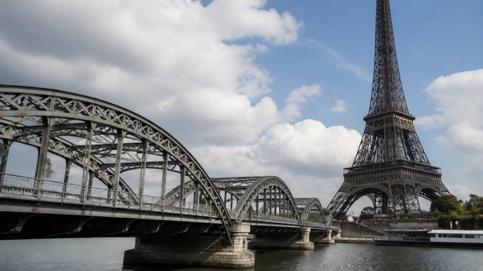
The Eiffel Tower made Eiffel’s structural method visible on an unprecedented scale. Designed by Maurice Koechlin and Émile Nouguier, developed with Stephen Sauvestre and constructed by Eiffel’s firm, the tower consists of four large legs that curve inward as they rise. The legs are connected by platforms, horizontal framing and extensive diagonal bracing, forming a three-dimensional lattice rather than a solid shaft.
Why the tower narrows and curves upward
The tower’s profile responds to the changing demands of gravity and wind. At the base, the legs are widely separated to provide a broad support footprint and resist overturning. Higher up, the structure narrows because the accumulated vertical load is lower and the required resisting lever arm changes. The curved profile also allows the main legs to align more closely with the dominant resultant forces produced by gravity and lateral action.
Member forces change with height and position. Lower legs carry substantial compression from the tower’s self-weight and applied loads, while diagonal and horizontal members transfer shear, restrain movement and stabilize the primary framing. Wind produces bending and overturning effects in addition to local forces in the lattice. The tower’s openness reduces exposed surface compared with a solid wall of the same outline, allowing much of the wind to pass through. That does not make wind behavior simple: turbulence, changing pressure over height, interaction between members and deformation still require careful consideration.
Triangulation, rivets, foundations, and erection
Triangulation gives the tower its structural discipline. Diagonal members subdivide each face into stable panels and limit racking, while the spatial arrangement of the four legs provides resistance in more than one direction. Riveted construction joined prefabricated iron components into a continuous frame. The quality of the finished structure depended on accurate shop work, consistent component dimensions and careful control of field connections.
The foundations were designed to transfer the large leg reactions into the ground, including vertical forces and effects associated with wind-induced overturning. The four bases were not simply points supporting a decorative object; they were part of the tower’s overall stability system.
Erection required the structure to remain stable while it was incomplete. Components were prepared in the workshop, transported to the site and assembled in stages. Hydraulic jacks and temporary adjustment arrangements were used where appropriate during the alignment and positioning of the legs and connecting work. Such devices did not replace structural calculation; they helped the builders bring accurately made components into their intended geometry and manage tolerances during construction.
This is the central lesson of Eiffel Tower engineering. Its architectural form is inseparable from its structural logic. The visible lattice expresses the paths by which forces travel, and the open members reveal how a large structure can achieve stiffness and stability without becoming a massive continuous wall.
Beyond the Tower: The Statue of Liberty and Nice Observatory
The Statue of Liberty’s flexible internal framework
Eiffel also contributed to the internal iron framework of the Statue of Liberty, working with a broader project team that included Bartholdi and other engineers. It is important not to describe him as the sole author of the monument. The copper skin, artistic design, project management and supporting structure emerged from a shared history of design decisions and fabrication.
The engineering challenge was to support a relatively thin outer skin without forcing it to behave like a rigid masonry mass. Eiffel’s internal frame provided a load-bearing skeleton, while secondary members and attachments connected the copper sheets to the structure. The framework was designed to permit relative movement and flexibility, allowing the skin and iron support to respond differently to temperature, wind and deformation.
This separation between enclosure and primary frame anticipated a principle familiar in modern façade engineering: components with different stiffness, thermal response and movement requirements should not be forced into identical behavior. The framework had to remain stable while accommodating differential movement and transferring wind effects without damaging the outer skin.
The Nice Observatory dome and specialized ironwork
The movable dome of the Nice Observatory shows Eiffel’s ability to apply ironwork beyond bridges and tall lattice structures. A rotating or movable enclosure must be light enough to operate while remaining stiff enough to maintain its shape and protect the opening and astronomical equipment. Its support system also has to manage concentrated reactions, movement and alignment.
The dome therefore presented a specialized combination of lightweight framing, curved geometry and mechanical operation. It illustrates that Eiffel’s contribution was not limited to one recognizable tower form. He developed structural solutions suited to the behavior of the system, whether the dominant problem was a bridge arch, a tall wind-exposed frame or a movable enclosure.
What Eiffel Changed in Structural Engineering
Eiffel’s legacy lies less in a single invention than in a disciplined way of connecting analysis, geometry and construction. His projects made load paths legible. They used triangulated systems to control deformation, curved forms to align with force, and lattice construction to obtain stiffness with comparatively little material. They also treated fabrication accuracy, transport and erection as part of the engineering brief.
Modern engineers can recognize several continuing principles. Rationalized load paths remain essential to avoiding ambiguous force transfer. Wind engineering now uses refined atmospheric models, wind-tunnel testing, computational analysis and detailed code provisions, but the need to understand changing exposure and dynamic response is unchanged. Modular fabrication and digital coordination extend Eiffel’s prefabrication practices with far greater precision.
There are also lessons for constructability, inspection and maintainability. Riveted ironwork required attention to joints, access and durability. Large lattice structures expose many connections and members to weather, making inspection a continuing part of performance. Today’s engineers have advanced materials, non-linear analysis, finite-element methods and formal reliability frameworks, but these tools do not remove the need for clear detailing and practical construction sequences.
In this sense, Eiffel helped move structural practice away from largely empirical assembly toward a more systematic relationship between assumed loads, calculated forces, geometry, material use and execution. He did not create modern structural engineering by himself, and his work should not be judged as though it followed present-day codes. Its importance is that it demonstrates the value of performance-based thinking before that term became standard.
Project Comparison: Structure, Forces, and Method
| Project | Structural challenge | Eiffel’s response | Engineering significance |
|---|---|---|---|
| Maria Pia Bridge | Long railway crossing over a deep valley and river | Large wrought-iron arch, open viaduct framing and staged erection | Demonstrated efficient arch action and integrated fabrication with construction |
| Garabit Viaduct | High, wind-exposed crossing with demanding access and erection | Large arch, triangulated supports, lateral bracing and controlled assembly | Connected geometry, compression behavior and temporary stability |
| Eiffel Tower | Extreme height, changing wind exposure and overturning effects | Four curved legs, open lattice, triangulation, riveted connections and staged erection | Made wind-responsive structural form publicly legible |
| Statue of Liberty framework | Support a thin outer skin while allowing differential movement | Independent internal iron frame with flexible connections and secondary support | Illustrated coordinated behavior between structure and enclosure |
| Nice Observatory dome | Lightweight movable enclosure requiring stiffness and alignment | Curved iron framing combined with a rotating support arrangement | Extended Eiffel’s methods to specialized mechanical and architectural structures |
Frequently Asked Questions
How did Gustave Eiffel design for wind?
Eiffel and his collaborators combined assumed wind pressures with open, tapered and triangulated forms. The lattice reduced the solid area presented to the wind, while bracing transferred lateral forces and restrained deformation. They also considered how exposure changed with height and how partly completed structures could remain stable during erection.
What was innovative about the Eiffel Tower’s structure?
The tower used four curved legs, extensive diagonal bracing and an open riveted lattice to create a tall frame with clear force paths. Its profile changed with height, responding to gravity, wind and overturning demands. Prefabricated components and controlled erection made the structural concept practical as well as visually distinctive.
Which bridges are most associated with Eiffel?
The Maria Pia Bridge at Porto and the Garabit Viaduct are especially associated with Eiffel’s firm and its development of large wrought-iron arch structures. Both projects combined compression-dominated geometry with open viaduct framing, lateral stability measures and demanding erection conditions. Their significance lies in the relationship between structural form and construction method.
Did Eiffel invent modern structural engineering?
No single engineer invented modern structural engineering, and Eiffel did not use contemporary codes or computational analysis. His contribution was methodological: he connected calculations, graphical reasoning, material efficiency, fabrication, transport and erection. Gustave Eiffel structural design is best understood as an important step toward systematic, performance-oriented practice.
Conclusion: Designing for Behavior and Construction
Gustave Eiffel structural design remains valuable because it begins with behavior. Eiffel’s bridges, tower, framework and dome show that wind-resistant structures are created by making forces legible, shaping the form around those forces and providing enough bracing to preserve geometry under changing conditions.
Structural engineers can also learn to account for erection as carefully as the final condition. Prefabrication, accurate connections and temporary stability are not merely project-management details; they determine whether a calculated structural system can safely become reality. Finally, Eiffel’s economical use of iron demonstrates that lightness should not be confused with weakness. A structure is efficient when its material is placed where it contributes to load transfer, stiffness, durability and stability.