BIM Clash Detection Tolerances: How to Prioritize Issues That Actually Affect Construction
Effective clash detection is not about producing the most warnings. It is about setting construction-informed rules that identify conflicts affecting installation, access, safety, sequencing, performance, and rework.
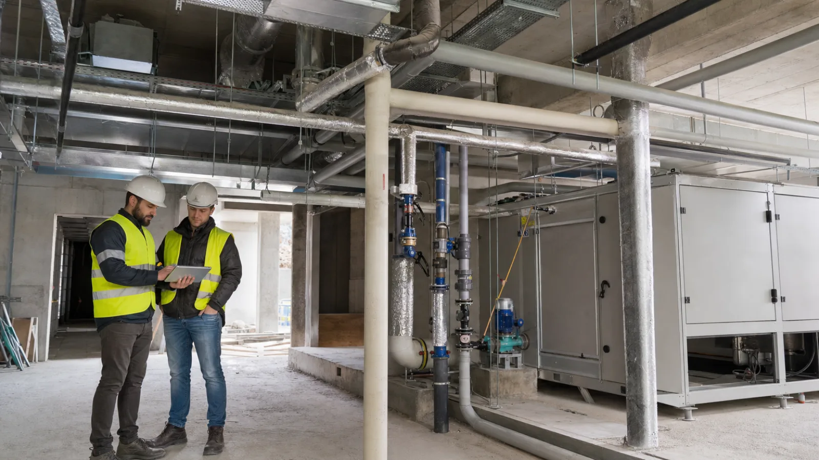
BIM clash detection tolerances determine when a geometric intersection, near miss, or clearance shortfall becomes an issue that requires action. Used well, they help project teams distinguish construction risks from harmless modeling variation. Used poorly, they produce long lists of alerts that obscure the conflicts most likely to affect installation, safety, access, sequencing, cost, or rework. Tools such as Solibri’s clash detection software can support the process, but software settings do not replace construction judgment.
The objective is not to detect every possible geometric relationship. It is to turn model conflicts into ranked, owned, and resolved construction decisions. That requires tolerances based on project requirements, system behavior, installation methods, manufacturer information, applicable requirements, and actual site constraints—not one universal number.
Key takeaways
- Separate direct intersections from installation, maintenance, access, replacement, and support clearances.
- Set each clash detection tolerance according to the system, project phase, model purpose, and source of the requirement.
- Prioritize issues by consequence, certainty, urgency, repetition, and coordination effort rather than raw alert count.
- Assign both a responsible trade and a decision owner, then record the outcome and re-test affected areas.
- Use field verification to confirm conditions that models, manufacturer data, or late changes cannot reliably represent.
What Are BIM Clash Detection Tolerances?
A BIM clash detection tolerance is a rule that defines when the relationship between modeled elements becomes actionable. A direct intersection between a structural beam and a pipe is different from a pipe passing close to a cable tray, and both are different from a service that technically fits but leaves no room for insulation, access, or replacement.
Three checks are commonly needed. A geometric intersection test identifies elements occupying the same modeled space. A proximity test identifies elements that are close enough to create an installation or sequencing concern. A clearance test checks whether a defined zone around an element remains available for operation, inspection, maintenance, safety, or removal.
The appropriate rule varies by system, trade, installation method, project phase, and information reliability. A fabricated duct assembly, a flexible cable route, a plant-room pump, and a temporary access route do not behave in the same way. A single tolerance applied to every category can therefore create misleading results.
Hard clashes versus soft clashes
Hard clashes are physical intersections between elements that should not occupy the same space. Examples include a pipe passing through a beam without a designed opening, a duct intersecting a wall where no penetration is allowed, or equipment overlapping another fixed object.
Soft clashes concern space needed around an element rather than the element’s solid geometry. They include access-panel zones, valve operation space, maintenance envelopes, equipment removal paths, fire or safety clearances, insulation allowances, and installation zones. These issues may be more consequential than a simple geometric intersection because a system can be impossible to install, inspect, operate, or maintain even when its primary solids do not overlap.
Why Default Tolerances Create Too Many False Positives
False positives often originate in the models rather than in the clash engine. Overly detailed geometry, placeholder objects, duplicate elements, inconsistent model origins, linked-model offsets, generic fittings, and unmodeled insulation can all create alerts that do not represent a practical construction problem.
Small discrepancies may result from different modeling conventions or coordination-stage approximations. A generic fitting may extend beyond the space occupied by the procured component. A temporary placeholder may be included in a model exchange even though it is excluded from the current test. A support may appear to conflict because the model does not yet represent the approved support strategy.
The opposite risk is equally serious. Suppressing broad categories of clashes or selecting a large tolerance without trade review can hide a condition that prevents installation or compromises system performance. A tolerance is not permission to ignore a known constraint. It is a documented rule for deciding when a condition needs review.
How to Set a Tolerance Framework That Reflects Construction Reality
Start with project requirements and model purpose
First identify why the test is being run. Design coordination, tender review, fabrication coordination, installation release, and as-built validation have different information needs. A design-stage model may support route-level coordination, while a fabrication or installation model may need verified fittings, supports, insulation, access zones, and manufacturer-specific geometry.
Separate design coordination rules from fabrication or installation verification rules. Before selecting values, review the project BIM execution plan, coordination specification, applicable codes and requirements, manufacturer data, access provisions, and trade responsibilities. The source of every important clearance should be recorded so that later changes can be evaluated rather than treated as arbitrary settings.
Classify systems and constraints before choosing values
Group elements by the construction questions they create. Useful categories include structural elements, architectural assemblies, mechanical services, electrical services, plumbing, fire protection, equipment, supports, access zones, and temporary works.
Rigid elements, flexible services, insulation, supports, hangers, access panels, valves, dampers, equipment doors, and replacement paths require different checks. A pipe route may fit geometrically but fail when insulation and support space are included. A packaged unit may fit in its room but have no viable path for delivery or future replacement. A ceiling service zone may be coordinated while leaving no safe sequence for installing the systems above it.
Do not prescribe universal numeric tolerances. Instead, document the reason and source for each rule, such as a manufacturer requirement, a project specification, an installation method, a required access zone, or an agreed trade constraint.
Separate hard-clash rules from clearance rules
Configure direct intersection tests separately from proximity and clearance-zone tests. This makes the result easier to interpret and prevents a legitimate maintenance envelope from being confused with a physical collision.
Clearance rules should identify whether the space is required for safety, operation, maintenance, installation, sequencing, or future replacement. One-way clearances may be appropriate where access is needed from a particular side. Installation zones may need to follow the path used to assemble or place an object, not just the space occupied after installation.
| Check type | Typical construction question | Consequence of missing it | Recommended treatment |
|---|---|---|---|
| Physical intersection | Do two elements occupy the same space? | Installation may be impossible or a penetration may be wrongly located. | Run as a direct hard-clash test and confirm design intent before closure. |
| Installation clearance | Is there enough room to place, connect, support, or assemble the system? | Work may require redesign, temporary removal, or unsafe installation. | Model or reference the installation zone and review with the responsible trade. |
| Maintenance access | Can personnel reach valves, filters, panels, controls, and inspection points? | Operation, inspection, or maintenance may be restricted. | Use element-specific access zones tied to project or manufacturer requirements. |
| Equipment removal path | Can major equipment or replaceable components be removed? | Future replacement may require demolition or major rework. | Check the route, turning space, doors, hatches, and sequence as a separate test. |
| Insulation or finish allowance | Does the coordinated route include the final build-up? | Services may become too close after insulation, cladding, lining, or finishes. | Use the specified build-up or an approved proxy and identify assumptions. |
| Support or hanger coordination | Can the system be supported without conflicting with structure or other services? | Field rerouting, added steel, or delayed installation may result. | Review representative support conditions and repeated locations, not only main runs. |
A Practical Method for Prioritizing Clash Issues
Issue count alone is not a useful measure of coordination quality. A model can contain many low-consequence alerts and only a few conflicts that threaten a critical installation release. Clash prioritization should combine consequence, certainty, time sensitivity, and coordination effort.
Rank by construction impact
- Safety or compliance: Give immediate attention to conditions that may affect safe access, required separation, fire protection, emergency operation, or other applicable requirements.
- Physical installability: Ask whether the work can actually be installed with the proposed sequence, tools, lifting method, supports, and connection space.
- System performance and access: Consider airflow, drainage, equipment operation, inspection, serviceability, and access to controls or isolation points.
- Schedule exposure: Elevate issues affecting critical-path work, prefabrication, procurement, embedded items, sleeves, openings, or installation release.
- Cost and rework: Prioritize conflicts likely to cause redesign, fabrication changes, demolition, remobilization, or substantial field modification.
- Repetition: A moderate issue repeated across many rooms, risers, or prefabricated assemblies can become a major production problem.
- Certainty: Distinguish confirmed conflicts from alerts caused by placeholders, unreliable geometry, or incomplete information. Uncertain issues should be validated, not automatically dismissed.
Use severity levels that lead to action
A practical clash severity matrix can use critical, high, medium, low, and informational levels. The labels matter less than the action attached to each one.
- Critical: Resolve or formally escalate before affected procurement, fabrication, installation release, or critical-path work proceeds.
- High: Assign an owner and due date for prompt design or trade coordination because the issue has a credible effect on installability, access, safety, or sequence.
- Medium: Resolve during the current coordination cycle unless a documented review confirms that the condition is acceptable.
- Low: Track and address through normal model development, while checking whether the issue is repeated.
- Informational: Record for awareness or future model refinement without presenting it as an unresolved construction obstruction.
A low-severity issue may still require escalation if it is embedded in a repeated prefabricated assembly or appears throughout a building. Conversely, an isolated alert caused by an unapproved placeholder may be lower priority than its geometry suggests.
Assign ownership instead of sending anonymous alerts
Every issue should identify the responsible trade, affected trade, design authority, and decision owner. Correcting the model and making the design decision are not always the same responsibility.
Useful issue fields include location, element identifiers, a plan or section reference, a 3D snapshot, the rule triggered, observed relationship or clearance, required outcome, responsible party, decision owner, due date, status, and resolution note. This information allows the team to distinguish a corrected model from an accepted condition, a deferred decision, or a confirmed false positive.
Model Quality Requirements Before Running Clash Tests
Clash results cannot be trusted when models are not aligned, current, or sufficiently developed. Before testing, verify shared coordinates, units, levels, model versions, duplicate geometry, object classification, naming, system connectivity, and design status.
Identify placeholders, exclusions, temporary objects, and elements intentionally outside the coordination scope. Confirm that linked models use the agreed origin and that model exchanges follow a documented schedule. A model readiness checklist should state which disciplines are included, what level of information is expected, what areas are excluded, and which assumptions remain unresolved.
Model quality for clash detection also includes meaningful system relationships. A disconnected pipe, generic equipment object, or incomplete support layout can produce a technically clean result that is not useful for construction. Coordination teams should therefore review both geometry and information before interpreting the alert count.
A Coordination Workflow That Converts Clashes Into Decisions
Prepare and filter
Establish test matrices by trade and avoid comparing objects that cannot produce meaningful results. For example, certain temporary or intentionally embedded relationships may need separate review rather than inclusion in a general hard-clash test.
Use rule-based exclusions carefully and document every exclusion. Group duplicate or repeated issues so the team can address the root cause without losing location-level traceability. A single design decision may resolve many alerts, but the affected locations should remain visible for verification.
Review and validate
The BIM coordinator should review automated results before issuing them. Visually inspect representative issues and confirm that the model versions, tolerances, object classifications, and test scope are correct. Trade specialists should review issues involving installation sequence, supports, fabrication, access, lifting, or manufacturer constraints.
A useful review asks: Is the conflict real? Is the required clearance represented correctly? Does the proposed solution work in plan, section, and three dimensions? Could the change create a problem at another location or stage of work?
Resolve and close
Require a decision, not merely a status change. Record whether the issue was corrected, accepted with justification, deferred, or identified as a false positive. Re-run affected tests after changes and verify that the resolution did not create a new conflict elsewhere.
How Coordination Meetings Should Discuss Tolerances and Priorities
Meetings should focus on high-impact clusters, root causes, and upcoming work releases rather than scrolling through every alert. Use plan, section, 3D, and sequencing views to show why a conflict matters and what decision is needed.
When a tolerance is adjusted, record who approved the change, why it was changed, which rule it affects, and which model versions it applies to. Escalate unresolved issues that affect procurement, fabrication, installation release, embedded items, or critical-path work. A tolerance decision should remain traceable after the meeting, especially when different phases use different rule sets.
Metrics That Show Whether Clash Detection Is Working
Useful measures include open issues by severity, aging of critical issues, repeated or duplicate issues, false-positive rate, time to decision, issues reopened after closure, and clashes discovered after installation. These measures reveal whether the process is producing timely and reliable decisions.
Reducing the raw clash count is not automatically success. A lower count may simply reflect aggressive exclusions or incomplete models. The stronger question is whether important issues are being identified early, assigned to the right people, decided before work is released, and prevented from recurring.
When Model Review Must Be Confirmed in the Field
A coordinated model does not replace surveying, layout verification, sleeves and embeds checks, manufacturer information, or site inspection. Field confirmation is especially important where existing conditions are uncertain, design changes are late, prefabricated assemblies are being installed, plant rooms are tight, or work proceeded before the latest model exchange.
Field feedback should be returned to the coordination process. Repeated site discoveries may indicate a missing clearance rule, a weak model requirement, an unreliable survey input, or a sequencing assumption that needs to be made explicit in future exchanges.
BIM Clash Detection Tolerances: A Practical Checklist
- Define the purpose and project phase of each test.
- Confirm coordinates, versions, units, scope, and model readiness.
- Separate hard, soft, access, maintenance, replacement, and installation checks.
- Document the source of each tolerance or clearance requirement.
- Apply filters and exclusions only for documented reasons.
- Rank issues by consequence, certainty, repetition, and urgency.
- Assign both trade ownership and decision ownership.
- Validate representative results manually with relevant specialists.
- Re-test affected areas after model or design changes.
- Track false positives, repeat issues, reopened items, and field discoveries.
Frequently Asked Questions
What is a BIM clash detection tolerance?
It is a documented rule that determines when an intersection, proximity condition, or clearance shortfall becomes actionable. The rule may relate to physical geometry, installation space, maintenance access, equipment removal, insulation, safety, or system operation. Tolerances should reflect the project phase, system behavior, installation method, manufacturer information, and applicable requirements rather than a universal value.
What is the difference between a hard clash and a soft clash?
A hard clash is a direct geometric intersection between elements that should not occupy the same space. A soft clash involves a required zone around an element, such as space for access, maintenance, installation, insulation, operation, or replacement. Soft clashes can prevent construction or future servicing even when the modeled solids do not physically intersect.
Should every discipline use the same clash tolerance?
No. Structural elements, flexible services, insulated pipework, cable trays, equipment, supports, and access zones have different construction behaviors and requirements. Rules should be organized by system and purpose. The team should also distinguish design-stage coordination from fabrication, installation, and as-built verification, because the required model reliability changes by phase.
How can teams reduce false positives in clash detection?
Improve model readiness before testing, including coordinates, versions, classification, duplicate geometry, placeholders, and design status. Separate hard intersections from clearance checks, use carefully documented exclusions, and visually validate representative alerts. Trade review is essential when generic geometry, installation sequence, supports, insulation, or manufacturer-specific constraints affect the practical meaning of a clash.
How should a construction team prioritize clash issues?
Rank issues by safety or compliance, physical installability, system performance, access, schedule exposure, cost, repetition, and certainty. Assign clear severity levels with required actions, not just labels. A repeated moderate issue may deserve more attention than an isolated high-looking alert, while an uncertain result should be validated before it is closed or suppressed.
Can clash detection replace field verification?
No. Model coordination cannot confirm every existing condition, survey point, late change, installation sequence, or manufacturer constraint. Field verification remains necessary for layout, sleeves, embeds, tight plant rooms, prefabricated assemblies, and work installed before the latest model exchange. Site findings should be fed back into model requirements and future clash detection rules.
Sources
- Project BIM execution plan, coordination specification, and agreed model exchange requirements.
- Current manufacturer installation, operation, maintenance, and replacement documentation for specified equipment.
- Applicable building, fire, electrical, mechanical, accessibility, and occupational-safety requirements adopted by the project.
- Approved trade installation methods, fabrication information, site surveys, and field verification records.
Conclusion
Effective BIM clash detection is not about generating the largest number of warnings. It is about identifying the conflicts that can affect installation, access, safety, system performance, sequencing, cost, and rework—and making sure those conflicts receive a timely construction decision.
Well-calibrated BIM clash detection tolerances, reliable models, construction-informed severity levels, clear ownership, and field feedback make coordination actionable. Teams reviewing their current rules should begin by separating hard clashes from clearance checks, documenting the source of each rule, and testing whether the highest-impact issues are being resolved before work is released.