Digital Image Correlation for Structural Testing: Measuring Strain, Cracks, and Deflection Without Contact
Digital image correlation gives structural testing teams a full-field view of deformation, crack development, and failure without attaching sensors to the specimen.
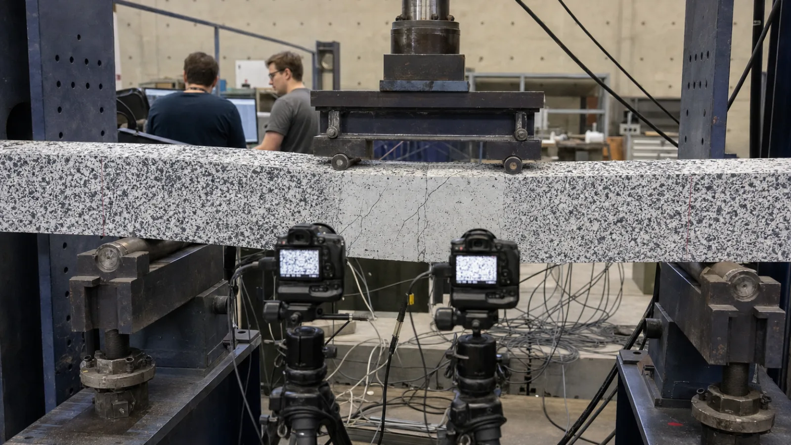
Digital image correlation, or DIC, is an optical measurement method that tracks how a visible surface changes during loading. In digital image correlation structural testing, cameras record a sequence of images while a specimen or component is pulled, compressed, bent, cycled, or otherwise loaded. Image-processing software converts changes in the surface pattern into displacement and strain data. Unlike bonded strain gauges or contact extensometers, DIC can measure across a broad area without physically touching the test article. Engineers evaluating equipment and digital image correlation measurement systems can use the method to compare full-field deformation with traditional point measurements.
The result is more than a video of a test. A properly designed DIC setup can show where deformation begins, how it spreads, when cracks localize, and whether actual behavior agrees with a numerical model. However, useful results depend on optical access, surface preparation, calibration, lighting, image quality, and disciplined data processing.
Key Takeaways
- DIC converts patterns recorded in successive images into full-field displacement and strain measurements.
- Two-dimensional DIC is appropriate for nearly planar motion; stereo 3D DIC is needed when out-of-plane movement or rotation is significant.
- Camera stability, calibration, lighting, speckle quality, spatial resolution, and processing settings determine measurement reliability.
- DIC can map crack initiation and development, but cracks that interrupt the surface pattern require careful interpretation.
- Full-field results are especially useful for comparing physical tests with finite element predictions and identifying incorrect assumptions about loads, restraints, or material behavior.
What Is Digital Image Correlation?
DIC compares successive digital images of a surface. The surface is given a random visual texture, usually a high-contrast speckle pattern. Software divides the reference image into small regions called subsets. It searches for the matching pattern in each later image and calculates how far that subset has moved.
Repeating this process across the field of view produces a displacement map. Spatial changes in displacement can then be used to calculate normal strain, shear strain, rotations, and other deformation measures. Because the method evaluates many locations at once, it is described as a full-field technique.
How image correlation converts photographs into measurements
A typical workflow contains four stages:
- Capture: Cameras record images at a suitable rate before, during, and after loading.
- Match: Software identifies the position of each surface subset in successive frames.
- Transform: Pixel movement is converted into physical displacement using scale and camera calibration.
- Differentiate: Displacement gradients are processed into strain fields and other engineering outputs.
The method measures the visible surface, not the internal material state. Its results therefore need to be interpreted alongside load, support conditions, actuator displacement, material properties, and any internal instrumentation.
2D and 3D DIC systems
A single-camera, or 2D, system is suitable when the surface remains approximately planar and motion is primarily in the image plane. It is comparatively simple and can provide high spatial resolution over a carefully selected region.
A stereo, or 3D, system uses two synchronized cameras viewing the same area from different angles. Triangulation reconstructs the three-dimensional position of surface points. This allows the system to measure out-of-plane movement and is generally more appropriate for beams, slabs, joints, curved components, buckling specimens, and tests where the surface may rotate.
What DIC Can Measure in a Structural Test
DIC is valuable because it combines several measurements in one coordinate system. Typical outputs include:
| Output | What it shows | Typical structural use |
|---|---|---|
| Displacement | Movement of surface points relative to a reference frame | Deflection, support movement, joint opening, and global deformation |
| Strain | Local change in displacement over distance | Elastic response, strain concentration, yielding, and localization |
| Crack opening or separation | Relative motion across a discontinuity | Crack initiation, propagation, width development, and failure mapping |
| Out-of-plane deformation | Movement normal to the observed surface | Buckling, delamination, plate bending, and three-dimensional failure modes |
Full-field results can reveal behavior that a small number of sensors may miss. A strain gauge might record a representative point, while DIC can show whether strain is uniform, concentrated around a hole, transferred near a connection, or interrupted by a crack.
Planning Digital Image Correlation Structural Testing
Camera selection and field of view
Camera choice should follow the test objective rather than a generic resolution target. A large specimen may require a wide field of view, while crack initiation or local strain concentration may require magnification. Increasing magnification improves the number of pixels across a feature but reduces the area that can be captured.
Important considerations include sensor resolution, lens quality, working distance, depth of field, frame rate, exposure time, synchronization, and available light. For rapidly changing events, the camera must capture images quickly enough to avoid missing the transition of interest. For slow static or quasi-static tests, spatial resolution and lighting stability may matter more than frame rate.
Mount cameras on a rigid support that is isolated from vibration and loading equipment. Even small camera movements can appear as specimen displacement. The camera view should also remain unobstructed throughout the expected range of motion.
Lighting, focus, and image capture
Uniform lighting helps the software distinguish the speckle pattern consistently. Avoid glare, reflections, flicker, deep shadows, and changing illumination. Matte surfaces are usually easier to image than glossy ones. Focus should be set on the measurement plane, and the aperture should provide enough depth of field without unnecessarily reducing light.
Capture a reference image before loading. The reference frame establishes the initial coordinates against which later images are compared. Include unloaded frames if the test requires evaluation of drift, seating, or thermal movement before the main loading sequence.
Surface preparation and speckle patterns
The surface must contain a pattern that remains visible and attached during testing. A common approach is a uniform light base coat followed by randomly distributed dark speckles. The pattern should not be periodic, overly dense, excessively large, or so faint that neighboring subsets look alike.
Pattern scale depends on camera resolution, field of view, and the smallest feature to be measured. A pattern appropriate for global beam deflection may not resolve a narrow crack or localized strain band. Before the formal test, inspect trial images at the intended magnification and loading distance.
For concrete, masonry, coated steel, composites, and other materials, confirm that the coating does not alter the surface behavior relevant to the test. Loose dust, moisture, peeling paint, and heavy texture can reduce correlation quality. The surface preparation method should be documented so the measurement can be reproduced.
Calibration and reference images
Calibration establishes the relationship between image coordinates and physical coordinates. In a 2D system, this typically includes scale and lens-related corrections. In a 3D system, calibration determines the relative camera geometry needed for triangulation.
Calibration should be performed with the cameras in the same position, focus, lens setting, and working distance used during the test. Repositioning a camera, changing zoom, or altering the lens can invalidate the calibration. Check calibration quality before loading and record the calibration file, target information, camera settings, and calibration date in the test record.
From Images to Engineering Results
Tracking subsets and calculating displacement
The analysis software searches for each subset in a later image. Subset size, step size, and search strategy affect both resolution and robustness. Larger subsets generally contain more texture information and can tolerate moderate pattern changes, but they smooth over small features. Smaller subsets can resolve finer details but may be more sensitive to noise and poor texture.
Step size controls the spacing between calculated points. A small step creates a dense result map but does not automatically create more accurate information. Effective spatial resolution is influenced by subset size, image quality, lens distortion, pattern scale, and processing settings.
Deriving strain fields
Strain is calculated from spatial gradients in the displacement field. Because differentiation amplifies noise, strain maps often require carefully selected smoothing or virtual gauge settings. Excessive smoothing can hide real localization; too little smoothing can produce a visually noisy field that is difficult to interpret.
Report the strain definition used, coordinate directions, subset and step sizes, smoothing parameters, and region of interest. Strain values should not be treated as independent point measurements when neighboring subsets overlap heavily. Analysis settings influence how sharply a concentration appears.
Filtering, smoothing, and region-of-interest choices
Remove points affected by shadows, glare, damaged paint, occlusion, or loss of correlation. A valid-looking color map can still contain unreliable areas if correlation confidence is not reviewed. Use masks to exclude grips, fixtures, background objects, and surfaces that move independently of the test article.
Review both the processed data and the original images. If a suspicious strain band appears, determine whether it corresponds to a physical feature, a crack, a changing shadow, a pattern defect, or a processing artifact.
Measuring Cracks and Localized Damage
DIC can identify crack initiation by showing a sharp displacement discontinuity or a rapidly developing strain concentration. It can also track the relative movement of points on either side of a crack to estimate opening and sliding. This is useful in concrete, masonry, composite materials, welded components, bolted connections, and other systems where damage evolves across a broad area.
Crack measurements require appropriate spatial resolution. If the field of view is too large or the pattern is too coarse, a narrow crack may be represented by only a few pixels and its opening may be underestimated or missed. Conversely, a high-resolution local view may not capture the surrounding structural response.
Cracks can also interrupt the texture used for correlation. After cracking, subsets that cross the discontinuity may no longer match reliably. Analyze points on each side of the crack separately and use correlation confidence, displacement discontinuities, and synchronized load data to distinguish physical damage from tracking failure.
Accuracy, Resolution, and Common Limitations
DIC is not automatically more accurate than contact instrumentation. Its uncertainty depends on the complete measurement chain, from camera stability through surface preparation and processing. Accuracy should be verified against a known displacement, a calibrated translation stage, a reference gauge, or another suitable measurement method.
| Error source | Potential effect | Practical control |
|---|---|---|
| Camera vibration or movement | False displacement or apparent strain | Use rigid mounting, isolate vibration, and monitor fixed reference points |
| Lens distortion or poor calibration | Spatially varying measurement error | Calibrate in the final camera configuration and verify calibration quality |
| Glare, shadows, or changing light | Lost correlation and noisy results | Use diffuse, stable lighting and matte surface treatment |
| Weak or unsuitable speckle pattern | Incorrect tracking or reduced spatial resolution | Test pattern scale and contrast before the formal experiment |
| Out-of-plane motion in a 2D setup | Apparent in-plane strain or displacement | Use stereo 3D DIC where depth motion is expected |
| Excessive smoothing | Suppressed peaks and blurred localization | Compare multiple settings and report the selected parameters |
| Insufficient frame rate | Missed transient events or crack jumps | Match acquisition rate to the loading and failure process |
Temperature changes can affect cameras, lenses, specimens, and fixtures. Outdoor testing adds wind, changing sunlight, vibration, and atmospheric effects. Protective enclosures may help, but they can introduce reflections or reduce image quality. The environment should be treated as part of the measurement system.
Using DIC Results for Model Validation
DIC provides a strong basis for comparing physical tests with finite element or analytical models. Instead of comparing only ultimate load or displacement at one actuator point, engineers can compare displacement shapes, strain concentrations, crack paths, support rotations, and failure localization.
For a meaningful comparison, align coordinate systems and compare equivalent quantities. A model prediction at a node should not be compared casually with a heavily smoothed experimental average. Apply compatible gauge lengths, boundary conditions, load histories, and measurement regions. If the model predicts a strain concentration in one location but DIC shows it elsewhere, investigate material properties, connection behavior, boundary conditions, mesh sensitivity, and load introduction.
DIC can also help improve the model before formal validation. Full-field data may reveal that an assumed uniform material response is unrealistic or that a joint, interface, or contact condition controls the observed behavior.
Practical Test Workflow and Reporting Checklist
- Define the measurement objective, including the expected displacement scale, strain scale, crack size, and loading rate.
- Select 2D or 3D DIC based on expected motion and specimen geometry.
- Choose cameras, lenses, field of view, frame rate, lighting, and mounting locations.
- Prepare and inspect the surface pattern at the intended resolution.
- Calibrate the system without changing the final camera configuration.
- Capture unloaded reference images and synchronize images with load and actuator data.
- Run a preliminary check for vibration, glare, focus, occlusion, and correlation quality.
- Process the test using documented subset, step, filtering, smoothing, and region-of-interest settings.
- Review raw images, confidence measures, displacement maps, strain fields, and crack features together.
- Compare selected measurements with an independent sensor or known reference where practical.
- Report uncertainty, excluded regions, calibration information, and all material surface treatments.
Frequently Asked Questions
Is DIC better than strain gauges?
Neither method is universally better. Strain gauges can provide precise local measurements and work when optical access is limited. DIC measures a wider area, does not require bonding, and can reveal where the response changes. Using both can provide useful cross-checks when the test permits it.
Can DIC measure cracks in concrete?
Yes. DIC can identify crack initiation, map crack development, and estimate opening or sliding when the surface is visible and the camera resolution and speckle pattern are appropriate. Very narrow cracks, dust, spalling, and severe surface changes can reduce reliability.
Does DIC work in 3D?
Yes. Stereo DIC uses two synchronized cameras to reconstruct three-dimensional surface motion. It is useful when the specimen rotates, buckles, curves, or moves out of plane. A single-camera 2D system is suitable only when planar-motion assumptions remain valid.
What affects DIC accuracy?
Camera stability, calibration, lens distortion, focus, lighting, speckle quality, field of view, frame rate, subset settings, smoothing, out-of-plane motion, and temperature can all affect accuracy. Verification against an independent reference is recommended for important tests.
Can DIC be used outdoors?
Yes, but outdoor testing requires control of sunlight, shadows, wind, vibration, temperature, moisture, and camera protection. Stable lighting and rigid mounting are especially important. The setup should be checked throughout the test because environmental changes can alter image quality or introduce apparent motion.
Sources
- ASTM International, ASTM E2208: Standard Guide for Evaluating the Performance of Optical Strain Measurement Systems.
- W. H. Peters and W. F. Ranson, “Digital Imaging Techniques in Experimental Stress Analysis,” Optical Engineering.
- J. G. M. de Vree, J. J. C. Remmers, and R. de Borst, technical literature on full-field optical measurement and deformation analysis.
- M. A. Sutton, J. J. Orteu, and H. W. Schreier, Image Correlation for Shape, Motion and Deformation Measurements, Springer.
Conclusion
Digital image correlation extends structural testing from a few instrumented points to a visual map of how a component deforms and fails. It can measure displacement, strain, crack development, and out-of-plane movement without contacting the specimen. The method is most effective when the camera system, surface pattern, calibration, acquisition settings, and analysis workflow are designed around the engineering question.
For reliable results, treat DIC as a measurement system rather than simply a camera and software package. Validate the setup, document processing choices, understand spatial resolution, and compare optical data with loads and complementary sensors. Used with that discipline, DIC can improve experimental interpretation and provide detailed evidence for structural assessment and model validation.