How to Add a Balcony to an Existing Building: Structural Design, Dowels, Software and Construction Guide
How to Add a Balcony to an Existing Building: Structural Design, Dowels, Software and Construction Guide Adding a balcony to an existing building is a structural alteration
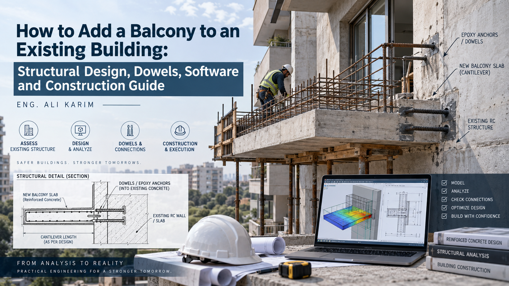
Adding a balcony to an existing building is a structural alteration, not simply an architectural extension. A new balcony introduces permanent weight, occupancy loads, wind effects, vibration, water exposure, and connection forces that must be transferred safely into the existing building.
For a reinforced-concrete building, the work typically involves investigating the existing slab, beams, columns, walls, reinforcement, foundations, and façade; selecting a support concept; designing the new concrete and steel; and detailing the interface between old and new construction. The final solution must also satisfy local building regulations, fire requirements, waterproofing standards, and construction tolerances.
This guide explains the engineering process from initial assessment and load calculations through dowel design, software modeling, anchorage, detailing, waterproofing, and site execution. A licensed structural engineer should verify the design and adapt it to the building’s materials, condition, location, and governing design code.
1. Start with a structural assessment
The first step is to understand what already exists. Original drawings are useful, but they should not be treated as conclusive because buildings may differ from their construction documents, reinforcement may have been changed, and deterioration may have developed over time.
Review available information
- Architectural, structural, and construction drawings
- Original concrete and reinforcement specifications
- Records of alterations, repairs, or previous extensions
- Building age, occupancy, and exposure conditions
- Information about settlement, cracking, corrosion, or water ingress
- Local permit, planning, fire, and accessibility requirements
The engineer then performs a site inspection. The inspection should identify the existing floor system, slab thickness, beam and wall locations, façade construction, support conditions, cracks, deflection, corrosion, and access constraints. The proposed balcony location must be checked from inside and outside the building because finishes, ceilings, services, insulation, and façade elements can hide the structural members needed for a safe connection.
Locate existing reinforcement and services
Before drilling or cutting, the team should map reinforcement and embedded services. Ground-penetrating radar, cover meters, electromagnetic scanners, selective opening-up, and carefully controlled core drilling can help establish the position, diameter, spacing, and depth of existing bars. Service detection is equally important: electrical conduits, plumbing, gas lines, post-tensioning tendons, and mechanical systems must not be damaged.
Concrete strength may be estimated from records and confirmed with testing where necessary. Depending on the building and the design risk, investigations may include rebound or ultrasonic testing, concrete cores, carbonation assessment, chloride testing, and corrosion inspection. The engineer must also determine whether the existing concrete is sound enough to receive new anchors or reinforcement.
2. Select the balcony support concept
The structural arrangement controls the loads, connection forces, appearance, construction method, and cost. The most common options are a cantilevered balcony, a balcony supported by posts or columns, a balcony hung from above, or a balcony carried by beams connected to the existing structure.
Cantilevered balcony
A cantilevered balcony projects from the building without visible supports below. It can provide a clean architectural appearance, but it creates substantial negative bending moment and shear at the building interface. The existing slab, edge beam, wall, or frame must be capable of receiving these forces, or the design must introduce new internal supports and reinforcement.
A new slab simply bonded to the face of an existing slab is rarely an adequate cantilever connection. A cantilever requires a continuous tension load path near the top of the support region, compression transfer through the concrete, adequate shear resistance, and sufficient development or anchorage of the reinforcement.
Balcony on posts or columns
Posts can reduce the moment transferred into the existing building because much of the vertical load travels directly to foundations. However, the posts require adequate footings or a verified load-bearing support below. They may also affect parking, circulation, drainage, property boundaries, and the building’s architectural appearance.
Hung or bracket-supported balcony
Suspended balconies and steel bracket systems can be effective where a cantilevered concrete solution is impractical. Their anchors must resist tension, shear, prying, fatigue, and environmental exposure. The supporting floors, beams, walls, or roof structure must be checked for the concentrated forces introduced by the hangers or brackets.
Independent balcony structure
An independent steel or reinforced-concrete frame can minimize intervention in the existing building. It still requires a stable foundation system, movement detailing, a controlled interface with the façade, and careful management of differential settlement and thermal movement.
3. Establish the design loads
Balcony design should account for all actions that can affect the new structure and its connection to the existing building. The exact values depend on the applicable building code, occupancy, climate, geometry, and materials.
- Dead load: self-weight of the slab, beams, finishes, screed, waterproofing, ceiling systems, balustrades, planters, and fixed equipment.
- Imposed load: people, furniture, movable items, and the occupancy category specified by the code.
- Line loads: loads from masonry, façade elements, partitions, or balustrades applied along an edge.
- Guard and handrail loads: horizontal and vertical forces applied at the required height and spacing.
- Snow load: where applicable, including drifting, accumulation, and snow retention effects.
- Wind load: pressure and suction on the slab, soffit, screens, glazing, privacy walls, and balustrades.
- Seismic load: where required, including diaphragm interaction, anchorage, and relative movement.
- Construction loads: temporary storage, workers, formwork, wet concrete, equipment, and incomplete support conditions.
- Water and drainage effects: ponding risk, saturated finishes, and blocked drainage conditions where relevant.
Load combinations are then created for ultimate strength and serviceability conditions. The engineer checks bending, shear, torsion, axial effects, local bearing, anchorage, deflection, vibration, crack width, and durability. A balcony can be structurally strong yet unsuitable if it feels excessively flexible, drains poorly, or develops unacceptable cracks.
4. Check the existing building and its load path
The new balcony loads must be traced from the slab or framing system into the existing structure and ultimately to the foundations. This load path may pass through a façade beam, floor slab, wall, column, transfer beam, or several connected members.
For an existing reinforced-concrete slab, the engineer should check flexure in both directions, one-way and punching shear where relevant, local bearing, reinforcement development, crack control, deflection, and the capacity of the supporting beam or wall. For a frame-supported balcony, the supporting beam-column joint and the columns below may require review. Additional loads can also affect foundation pressure and settlement, even when the balcony itself appears small.
Existing members should be assessed using realistic material properties and current condition. Reduced section due to corrosion, concrete delamination, previous openings, unrecorded alterations, or reinforcement laps can materially change capacity. The engineer should not rely on visual appearance alone.
5. Design the connection between new and existing concrete
The connection is often the most critical part of a balcony addition. It must transfer the required shear, tension, compression, and moment while accommodating construction tolerances and the difference between new and older concrete.
Construction joint or structural connection?
A cold joint between two pours does not automatically create a moment-resisting structural connection. If the balcony is intended to act monolithically with an existing slab or beam, the design must specify how forces cross the interface. This may involve dowels, post-installed reinforcing bars, steel plates, headed anchors, corbels, brackets, or a new beam-and-column system.
The concrete interface may require removal of weak surface material, controlled roughening, cleaning, and preparation to achieve the assumed shear-friction behavior. The design should state whether the interface is intentionally roughened, what surface condition is required, and how the joint will be protected during construction.
Dowels and post-installed reinforcement
Dowels are bars or anchors that connect the new balcony to the existing structure. They can transfer shear, restrain separation, provide tension continuity, or help develop a new reinforcing cage. Their role must be defined in the design; placing a few bars into drilled holes does not by itself guarantee a safe connection.
Post-installed reinforcing bars are commonly installed by drilling holes into existing concrete, cleaning the holes, injecting an approved chemical anchoring adhesive, and inserting bars to the specified embedment. The design must consider:
- Required bar diameter, grade, spacing, and embedment depth
- Concrete strength, cracking condition, and edge distances
- Bar development length and lap length
- Concrete cone failure, pullout, splitting, pryout, and steel failure
- Shear transfer across the interface and shear-friction reinforcement
- Drilling tolerances and the risk of striking existing reinforcement
- Temperature, moisture, hole condition, and adhesive installation limits
- Fire, durability, corrosion protection, and inspection requirements
Where a dowel is intended to develop significant tension or bending continuity, the embedment length must be justified by the applicable code and the selected anchoring system’s technical approval. Short embedment should never be assumed to provide full continuity. The engineer may need to use several rows of bars, a deeper beam connection, a steel seat, or an independent support system when the existing member cannot provide adequate development length.
Mechanical anchors and steel connections
Post-installed mechanical anchors may be suitable for brackets, plates, handrail supports, or some structural connections. Their capacity depends on anchor type, diameter, spacing, edge distance, base material, cracked or uncracked concrete, installation torque, and load direction. Tension and shear interaction, group effects, eccentricity, and concrete breakout must be checked.
Steel plates and brackets should be detailed for force distribution rather than attached with isolated fasteners at the edge of a thin slab. Welds, bolts, stiffeners, corrosion protection, fire protection, and access for tightening must be included in the design. Where the connection is exposed to weather, water traps and crevices should be avoided.
6. Model the balcony with appropriate software
Structural software can improve analysis, but the model is only as reliable as its assumptions. The engineer should first define the intended load path and then select a model that represents the actual support and connection behavior.
A simple cantilever may be represented with beam and shell elements, while a balcony supported by beams, walls, columns, or brackets may require a three-dimensional frame or finite-element model. The model should reflect slab thickness, stiffness, support releases, torsional behavior, openings, edge beams, construction joints, and the actual connection stiffness where it is known.
Typical software tasks include:
- Applying permanent, imposed, wind, snow, seismic, and construction loads
- Generating code-based ultimate and serviceability combinations
- Reviewing bending moments, shear forces, torsion, reactions, and deflections
- Designing slab, beam, wall, and edge reinforcement
- Checking vibration and crack-control requirements
- Evaluating anchor groups and post-installed reinforcement
- Reviewing the effect of support flexibility and differential movement
Finite-element results should be interpreted carefully near supports, corners, openings, concentrated anchors, and abrupt changes in stiffness. Mesh refinement, local peaks, boundary conditions, and load application areas can significantly affect the output. Software does not replace engineering judgment, hand checks, site verification, or a clear reinforcement detail.
7. Detail reinforcement and movement
Reinforcement detailing should make the calculated load path buildable. In a cantilever, the principal tension reinforcement is generally concentrated near the top of the support region, while the outer span and free edge require reinforcement for distribution, shrinkage, temperature effects, and local loads. The exact arrangement depends on the structural system and design code.
Details should show bar sizes, spacing, bends, anchorage, laps, cover, couplers, starter bars, edge reinforcement, openings, and the relationship between new and existing bars. Reinforcement must be supported so that it remains in the specified position during concrete placement. Congested connections should be reviewed for concrete flow, vibration access, and inspection.
The balcony should also be checked for relative movement. New concrete shrinks as it cures, steel and concrete expand and contract with temperature, and the existing building may move under live load, wind, or settlement. A rigid connection may be appropriate for a structural cantilever, while a façade seal, movement joint, or sliding detail may be required at nonstructural interfaces. Movement joints must not interrupt the intended structural load path.
8. Design waterproofing and drainage with the structure
Waterproofing is a structural durability issue as well as a finishing concern. Water entering the balcony connection can corrode reinforcement, damage interior finishes, and weaken the interface over time.
The design should provide a positive drainage slope, a durable waterproofing layer, properly formed edges, drip details, compatible sealants, and a reliable outlet. Thresholds and door openings require special attention because the finished balcony level must drain away from the building without creating an inaccessible step or a water entry point.
Balustrade posts should preferably be fixed in a way that does not puncture the primary waterproofing layer. If penetrations are unavoidable, they need proprietary sleeves, upstands, collars, or fully detailed flashing. The balcony edge should prevent water from running back onto the façade, and the connection should be protected from freeze-thaw action and chloride exposure where those conditions apply.
9. Plan the construction sequence
Construction sequencing can change the forces in the existing building. Temporary works may be required to support the new balcony, protect the façade, control demolition, or prevent overloading before the concrete reaches its specified strength.
Typical sequence
- Confirm permits, approved drawings, temporary works, material specifications, and inspection requirements.
- Survey the existing structure and mark the balcony position, levels, reinforcement, and services.
- Install temporary protection and shoring where specified by the engineer.
- Remove finishes or façade materials carefully to expose the structural connection zone.
- Scan and drill for dowels or anchors using the approved diameter, depth, alignment, and equipment.
- Clean drilled holes exactly as required by the anchoring product and document installation conditions.
- Install post-installed reinforcement or anchors, observing adhesive working time and curing limits.
- Fix new reinforcement, formwork, edge details, drainage components, sleeves, and embedded items.
- Inspect reinforcement, cover, connection preparation, and formwork before placing concrete.
- Place, compact, finish, and cure the concrete according to the specification.
- Maintain temporary support until the engineer confirms that the required strength and connection performance have been achieved.
- Install waterproofing, screed, finishes, balustrades, sealants, and façade interfaces.
- Complete inspections, water testing where specified, anchor records, and as-built documentation.
Concrete removal should be controlled to avoid damaging existing reinforcement or reducing the capacity of the supporting member. Chiseling, saw cutting, drilling, and demolition limits should be stated in the method statement. If unexpected reinforcement, voids, weak concrete, or services are found, work should stop in the affected area until the engineer reviews the condition.
10. Inspection and quality control
A balcony connection is difficult to inspect after it has been concealed. Hold points should therefore be established before drilling, after hole preparation, after anchor installation, before concrete placement, and before waterproofing covers the structural interface.
Inspection records may include reinforcement surveys, concrete test results, anchor product certificates, hole-cleaning records, adhesive batch numbers, installation temperatures, curing times, torque records, proof tests, photographs, and concrete placement reports. Anchor testing should be specified by the engineer and performed by qualified personnel; a site pull test cannot replace correct design or installation.
The completed balcony should be reviewed for cracking, deflection, drainage, sealant continuity, balustrade stability, and signs of water entry. Any deviation from the approved design should be documented and assessed before the balcony is placed into service.
11. Common mistakes to avoid
- Assuming the existing slab can carry the balcony without checking its reinforcement and supports.
- Attaching a new slab to the façade without designing a complete moment and shear load path.
- Using dowels with insufficient embedment, edge distance, or development length.
- Drilling without locating existing reinforcement, tendons, or services.
- Relying on adhesive anchors without following hole-cleaning and curing requirements.
- Ignoring the effect of new reactions on columns, walls, foundations, or adjacent floors.
- Designing the structure without accounting for balustrade, planter, snow, wind, or construction loads.
- Allowing waterproofing penetrations or door thresholds to be resolved only after construction.
- Using a software model with unrealistic supports or stiffness and accepting results without engineering review.
- Pouring concrete before inspecting reinforcement, embedment, cover, formwork, and connection preparation.
Conclusion
Adding a balcony to an existing building is feasible when the structural assessment, connection design, construction method, and waterproofing strategy are developed as one coordinated solution. The central engineering issue is the load path: every permanent, live, wind, snow, seismic, and guard load must travel through verified materials and connections into a structure and foundation system that can safely resist it.
Dowels and post-installed reinforcement can create effective connections, but only when their embedment, development, spacing, edge distances, installation, and concrete condition are properly designed and inspected. Structural software supports this work by analyzing realistic models and load combinations; it does not replace site investigation or professional judgment. With accurate surveys, clear detailing, controlled construction, and documented inspections, a new balcony can be integrated safely and durably into an existing reinforced-concrete building.
