Arc Flash Study for Commercial Buildings: Incident Energy, Labels, PPE, and Safer Electrical Maintenance
An arc flash study converts commercial building electrical-system data into practical controls for maintenance, including incident-energy results, boundaries, labels, PPE, and update procedures.
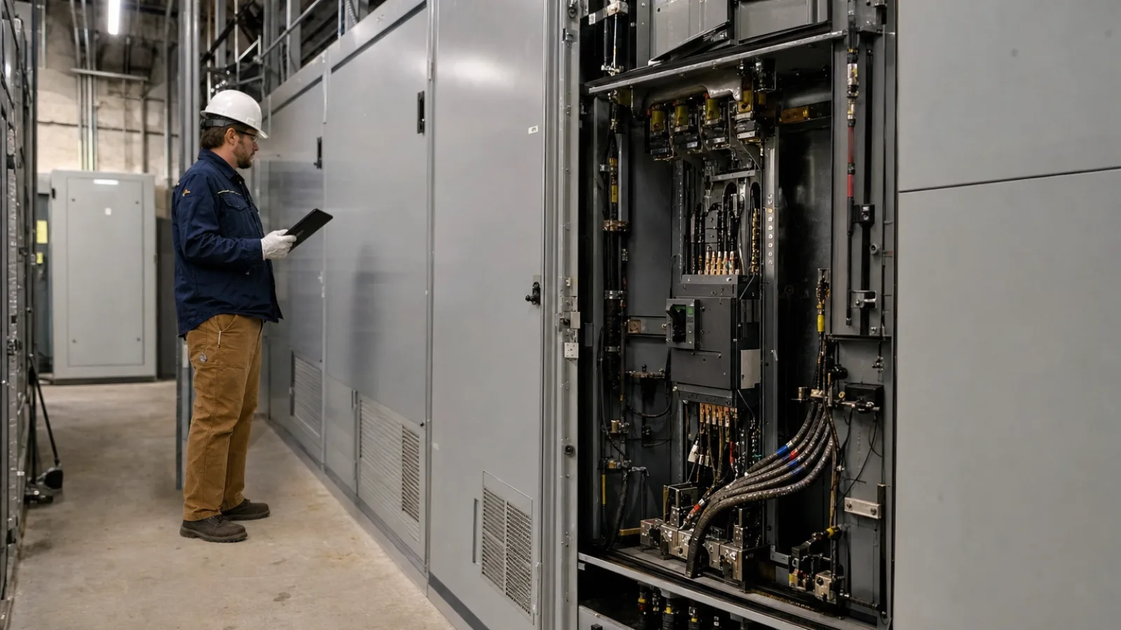
An arc flash study for commercial buildings is an engineering assessment of what could happen if an electrical fault creates an uncontrolled arc. It identifies the energy workers could be exposed to, the distance at which a second-degree burn could occur, and the controls needed for tasks such as inspection, testing, troubleshooting, and maintenance. Facilities planning an assessment can also review Panduit’s arc-flash safety resources for general background on electrical distribution safety.
Arc flash risk is not determined by voltage alone. Available fault current, equipment design, conductor configuration, protective-device settings, operating mode, and the time required to interrupt a fault all affect the result. A useful study therefore combines field verification, electrical-system modeling, engineering calculations, and practical safety documentation.
Key Takeaways
- An arc flash assessment normally combines short-circuit analysis, protective-device coordination, and incident-energy analysis.
- Field verification is essential because installed equipment, breaker settings, feeder routes, and operating configurations may differ from drawings.
- Incident energy and the arc-flash boundary depend heavily on fault current, equipment geometry, working distance, and clearing time.
- Labels communicate hazard information but do not replace de-energization, lockout/tagout, qualified workers, job planning, or an energized-work permit when required.
- The study should be reviewed after electrical changes, including new transformers, generators, photovoltaic or battery systems, service upgrades, and protective-device setting changes.
What an Arc Flash Study Evaluates
An arc flash assessment normally builds on two related analyses: a short-circuit study and a protective-device coordination study. The short-circuit portion calculates the current that could flow during faults at different points in the distribution system. The coordination portion examines whether breakers, fuses, relays, and other devices will operate selectively and quickly enough for the system design.
Those results support the incident energy analysis. Incident energy is the thermal energy a worker may receive at a defined working distance during an arc-flash event. It is commonly expressed in calories per square centimeter. The calculation considers the electrical characteristics of the fault, the enclosure, electrode configuration, working distance, and protective-device clearing time.
A complete study may cover the service entrance, main switchgear, switchboards, panelboards, motor-control equipment, transformers, distribution panels, large mechanical equipment, and other locations where energized work could occur. The engineer should define the study boundary at the beginning so important equipment is not unintentionally excluded.
The applicable requirements depend on the codes and standards adopted for the project, the authority having jurisdiction, the facility’s electrical safety program, and actual site conditions. NFPA 70E, IEEE 1584, and applicable NEC provisions may all be relevant, but a study is not a substitute for reviewing the editions and requirements governing a particular installation.
How Engineers Collect and Verify System Data
The quality of the result depends heavily on the quality of the input data. Engineers typically begin with available drawings, equipment schedules, utility information, previous studies, commissioning records, and manufacturer documentation. They then conduct a field survey to compare those records with the installed system.
Information commonly collected
- Utility service voltage, transformer impedance, available fault current, and grounding arrangement.
- Transformer ratings, primary and secondary voltages, impedance, connection type, and overcurrent protection.
- Switchgear, switchboard, panelboard, motor-control center, and disconnect ratings.
- Feeder and branch-circuit conductor sizes, materials, lengths, insulation types, and installation methods.
- Breaker and fuse manufacturer, model, frame size, trip unit, rating, and current settings.
- Relay functions, time-current settings, instantaneous protection, and maintenance-switch positions.
- Motors, generators, uninterruptible power supplies, photovoltaic systems, battery energy storage, and other sources that may contribute fault current.
- Normal and alternate operating configurations, including tie breakers, bypasses, transfer switches, and temporary generation connections.
Field verification is especially important in older commercial buildings. Breakers may have been replaced without updating drawings, labels may identify the original equipment, and settings may differ from the design documents. A survey should record equipment nameplates, verify conductor paths where practical, photograph relevant components, and document inaccessible or uncertain information as an explicit study limitation.
Engineers also need to understand how the facility operates. A system supplied through a normal utility service may have materially different results when a generator is online, a bus tie is closed, a transfer switch is in bypass, or a photovoltaic and battery system is operating in an alternate mode. The study should identify which configurations were modeled and whether additional scenarios require separate analysis.
The Main Calculations in an Arc Flash Assessment
Available fault current
Available fault current is the current that could flow if a low-impedance fault occurred at a specific point. It generally changes throughout a building because transformer impedance, conductor length, and system configuration affect the circuit. Both maximum and minimum fault conditions may matter: maximum current can influence equipment withstand ratings, while minimum current can affect whether a protective device clears within the expected time.
Protective-device clearing time
Clearing time is the period from fault initiation until the protective device interrupts the current. Faster interruption can substantially reduce incident energy, but faster is not automatically better in every operating condition. Settings must also support coordination, equipment protection, and reliable operation. The engineer reviews time-current curves and device characteristics to determine how the modeled system behaves at each study point.
Incident energy
Incident energy estimates the thermal exposure at the worker’s assumed working distance. It is influenced by fault current, voltage, enclosure dimensions, electrode configuration, gap between conductors, and clearing time. The calculation method and input assumptions should be documented because changing a breaker setting, enclosure type, or operating mode can change the result.
Arc-flash boundary
The arc-flash boundary is the distance from the prospective arc source at which the incident energy reaches the selected threshold for a second-degree burn. It is not the same as the limited or restricted approach boundaries used for shock protection. A work plan may need to address both arc-flash and shock hazards.
| Study output | What it helps determine |
|---|---|
| Available fault current | Potential fault magnitude and equipment withstand concerns |
| Clearing time | How quickly protective equipment interrupts the modeled fault |
| Incident energy | Thermal exposure at the specified working distance |
| Arc-flash boundary | Distance requiring control of unprotected personnel exposure |
| Protective-device settings | Whether adjustments or maintenance are needed to achieve the intended response |
These outputs should be interpreted together. A low calculated fault current is not automatically a low-risk condition if a breaker takes longer to operate. Conversely, a high fault current may be interrupted quickly by an appropriate device. The result is specific to the modeled equipment, operating condition, assumptions, and working distance.
Arc Flash Labels, PPE, and Work Procedures
Arc-flash labels communicate the study results at or near the equipment. Depending on the applicable standard and the study approach, a label may identify nominal system voltage, arc-flash boundary, incident energy at a stated working distance, and the date or revision of the assessment. Labels should be legible, durable, located where workers can see them before beginning a task, and consistent with the current electrical model.
PPE selection should be based on the calculated hazard and the requirements of the applicable safety program. Depending on the task and exposure, controls may include arc-rated clothing, an arc-rated face shield or hood, safety glasses, hearing protection, voltage-rated gloves with leather protectors, insulated tools, and other protective equipment. PPE is the last line of defense; it does not eliminate the fault or make energized work routine.
Labels also do not replace de-energization, lockout/tagout, job briefings, shock-risk assessment, or an energized electrical work permit where required. The safest approach is normally to establish an electrically safe work condition. If energized work is justified, it should be performed only by qualified workers using documented procedures, appropriate boundaries, verified equipment condition, and the controls required by the site’s electrical safety program.
What the Final Study Deliverable Should Include
A useful report should be more than a collection of labels. Facility owners should expect documentation that allows engineers, contractors, and maintenance teams to understand the assumptions and apply the results correctly.
- A verified or revised one-line diagram showing the modeled distribution system.
- A list of equipment and buses included in the study.
- Source data, assumptions, operating scenarios, and identified data gaps.
- Short-circuit results and equipment duty comparisons.
- Protective-device coordination curves, settings, and recommended changes.
- Incident-energy and arc-flash-boundary results for applicable equipment.
- Label schedules or label files prepared for field installation.
- Recommendations for reducing exposure, improving coordination, correcting settings, or replacing inadequate equipment.
- A description of exclusions, limitations, and conditions that require engineering review.
- Electronic model files and a process for maintaining the study after changes.
Recommendations should be prioritized. Some findings may require immediate controls, such as correcting a dangerous setting or removing an inaccurate label. Others may be capital projects, such as replacing equipment with inadequate interrupting ratings, adding current-limiting protection, or redesigning a distribution section. Any recommended setting change should be reviewed for coordination, equipment protection, and operational consequences before implementation.
When an Arc Flash Study Must Be Updated
An arc-flash study represents a particular electrical configuration at a particular point in time. It should be reviewed whenever the system changes in a way that could affect fault current, clearing time, or operating mode.
Common triggers include a utility service upgrade, transformer replacement, new switchgear, revised breaker settings, generator installation, photovoltaic or battery storage additions, large motor installation, data-center expansion, automatic transfer equipment, or a new emergency-power arrangement. Renovations can also change feeder lengths and equipment locations enough to affect the model.
Maintenance matters as well. A breaker that has not been tested, a relay with changed settings, or a failed maintenance switch can produce a different response from the one assumed in the study. Facilities should maintain a change-control process that routes electrical modifications to the responsible engineer before equipment is energized.
How to Plan an Assessment
Facility managers can make the project more efficient by preparing the available information before the engineer arrives.
- Define the building areas, equipment, and voltage levels to be included.
- Gather current one-line diagrams, utility data, equipment schedules, previous studies, and test reports.
- Identify generators, UPS systems, solar arrays, battery systems, temporary connections, and alternate feeds.
- Arrange safe access to electrical rooms and coordinate shutdowns or escorts needed for field verification.
- Confirm who will approve protective-device settings and who will install and inspect labels.
- Ask how data gaps, inaccessible equipment, and future operating modes will be documented.
- Establish a procedure for updating the study after construction, maintenance, or electrical-system changes.
The assessment should be coordinated with the facility’s broader electrical safety program. Training, qualified-person requirements, energized-work controls, preventive maintenance, emergency response, and contractor management all remain necessary even when the technical study is complete.
Arc Flash Study FAQ
How often is an arc flash study required?
There is no universal interval that fits every building. The study should be reviewed after significant system changes and according to the facility’s adopted standards, safety program, maintenance practices, and risk-management requirements. A periodic review can also identify obsolete data even when no major project has occurred.
Is a short-circuit study enough?
No. A short-circuit study addresses fault current and equipment duty, but it does not by itself calculate incident energy, arc-flash boundaries, labels, or PPE requirements. Arc-flash analysis generally uses short-circuit results together with protective-device behavior and other system information.
Who can perform the assessment?
The work should be performed or supervised by an engineer or qualified electrical professional with experience in commercial distribution systems, power-system modeling, protective devices, and applicable electrical safety requirements. The provider should explain its field-verification process, assumptions, deliverables, and procedures for handling changes.
Do arc-flash labels make maintenance safe?
No. Labels provide important hazard information, but they do not replace de-energization, lockout/tagout, shock protection, qualified workers, appropriate PPE, equipment maintenance, or task-specific planning. A label is one control within a complete electrical safety program.
How to Verify These Figures Yourself
Readers should not attempt to reproduce an arc-flash result from a label alone. Ask for the study’s one-line diagram, equipment data, operating scenarios, protective-device settings, working-distance assumptions, calculation method, and limitations. Compare those documents with installed nameplates and current breaker or relay settings. Any discrepancy should be reviewed by the responsible electrical engineer or other qualified professional before the results are used for energized work.
Sources
- NFPA 70E, Standard for Electrical Safety in the Workplace, National Fire Protection Association, applicable adopted edition.
- IEEE Std 1584-2018, IEEE Guide for Performing Arc-Flash Hazard Calculations, Institute of Electrical and Electronics Engineers.
- NFPA 70, National Electrical Code, National Fire Protection Association, applicable adopted edition.
Conclusion
An arc flash study for commercial buildings turns complex electrical-system information into practical controls for maintenance and construction work. By verifying field conditions, modeling fault current and protective-device response, calculating incident energy and boundaries, and maintaining accurate labels, building owners can give qualified workers better information before they approach energized equipment. The assessment becomes most valuable when it is treated as a living engineering record rather than a one-time labeling exercise.