Hydropower Water Tunnels: Headraces, Pressure Shafts, and Engineering Risks
Hydropower water tunnels connect intakes, reservoirs, turbines, and outlets while controlling the movement and energy of water through complex terrain. This guide explains tunnel types, hydraulic and geotechnical design, construction risks, transient control, lining decisions, and operational safety.
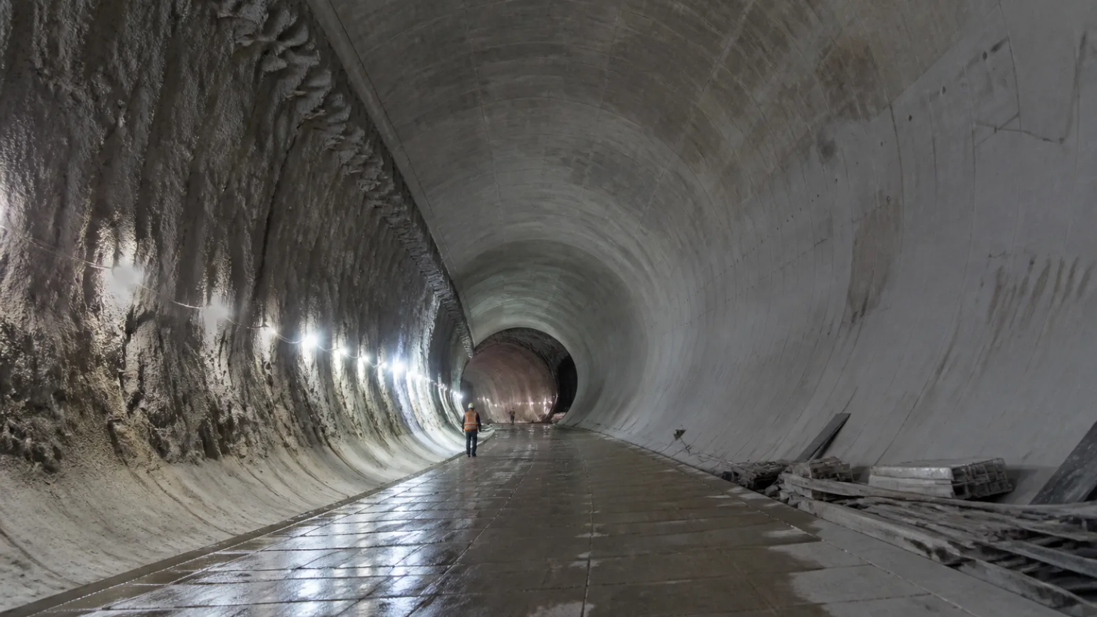
Hydropower water tunnels are underground passages that convey water between an intake, reservoir, river, turbine, and outlet within a hydroelectric scheme. They may carry water under a free surface or under pressure, depending on their location, profile, and operating function. Together with the intake, surge system, turbine, powerhouse, and tailrace, they form a connected hydraulic system rather than an isolated civil-works element.
Reliable performance depends on coordinating tunnel geometry, hydraulic behavior, ground conditions, structural support, construction methods, and operating controls. The tunnel must be compatible with the wider hydropower technology and equipment that controls and converts water energy. A design that performs well hydraulically may still be unsuitable if it is difficult to excavate, vulnerable to leakage, or unsafe to inspect and maintain.
What Are Hydropower Water Tunnels?
Hydropower water tunnels are engineered underground waterways used to move water through a power project. A typical arrangement may take water from a reservoir or river through an intake, convey it along a headrace, pass it through a pressure tunnel or pressure shaft, deliver it to turbines, and return the discharged water through a tailrace. Not every project uses all of these elements. The arrangement depends on topography, available hydraulic head, geology, environmental constraints, and the selected powerhouse location.
Underground conveyance can reduce surface disturbance and avoid long open channels across steep or inaccessible terrain. It can also allow an intake and powerhouse to be separated by substantial horizontal or vertical distance while maintaining an efficient water route. In mountainous schemes, tunnels may provide a more direct alignment than surface conveyance and can help protect the waterway from landslides, weather exposure, and competing land uses.
Hydraulic conditions vary along a tunnel. A headrace may operate with a free surface where air remains above the water, or it may run full under pressure. A pressure shaft is normally full and subject to transient loads when flow changes. A tailrace can be a pressurized tunnel, a free-surface passage, or a combination of structures leading back to the downstream water body. These distinctions affect lining, ventilation, drainage, access, and safety requirements.
Main Types of Water Tunnels in Hydropower Projects
Headrace tunnels
A headrace tunnel conveys water from an intake, reservoir, or forebay toward the powerhouse or a downstream pressure system. Its length and elevation influence the available generation head and the hydraulic losses in tunnels. A longer route can make a remote powerhouse practical, but it also increases friction losses, excavation quantities, construction duration, and exposure to geological uncertainty.
Designers must consider the tunnel profile, gradients, bends, changes in cross-section, sediment behavior, access points, and the relationship with surge-control structures. Depending on the scheme, the headrace may be designed for free-surface flow or as a pressure conduit.
Pressure tunnels and pressure shafts
Pressure tunnels and pressure shafts convey water while running full. A pressure shaft is usually vertical or steeply inclined and connects an upper waterway, surge structure, or reservoir system to turbines located at lower elevation. This arrangement can use a large hydraulic head while placing the powerhouse underground or at a protected location.
Because pressurized waterways are exposed to changing internal loads, their design must address pressure distribution, rock confinement, lining behavior, leakage, and transient events. Rapid changes in turbine discharge can produce water hammer, making the pressure shaft part of a wider surge-control system rather than simply a steep water passage.
Tailrace tunnels
A tailrace tunnel carries water away from the turbine and returns it to a downstream river, reservoir, or outlet channel. It must provide adequate discharge capacity while limiting backwater effects, turbulence, air entrainment, and energy losses that could affect turbine operation. The outlet geometry also needs to accommodate downstream water-level variation and protect the receiving water body from unacceptable erosion or recirculation.
Diversion and access tunnels
Temporary diversion tunnels route river flows around a construction area while dams, intakes, or other permanent works are built. They are designed for defined construction-phase flood conditions and may later be abandoned, plugged, or incorporated into another function. Permanent access and inspection tunnels provide routes for workers, equipment, drainage, ventilation, or future maintenance, but they are not necessarily part of the primary hydraulic conveyance system.
Key Design Considerations for Hydropower Water Tunnels
Hydropower tunnel design requires hydraulic calculations to be integrated with geological investigation, structural assessment, constructability planning, and operations analysis. The following issues are commonly addressed during concept and detailed design.
| Design issue | Why it matters | Typical engineering response |
|---|---|---|
| Design flow and velocity | Flow capacity, erosion, vibration, and operating efficiency depend on the relationship between discharge and tunnel area. | Assess normal, peak, minimum, and emergency flows; select a suitable section and verify velocity limits for the lining and waterway. |
| Hydraulic gradient and energy losses | Friction, bends, transitions, and roughness reduce the head available to the turbines. | Use hydraulic modeling to optimize alignment, diameter, roughness assumptions, transitions, and local fittings. |
| Tunnel diameter and alignment | Size affects capacity, excavation volume, pressure behavior, cost, and construction access. | Balance hydraulic performance with geology, excavation method, equipment constraints, and future maintenance needs. |
| Free-surface versus pressurized flow | The flow regime changes ventilation, lining loads, transient behavior, and minimum operating levels. | Define normal and transient water levels and verify that the tunnel remains stable under all credible operating conditions. |
| Intake and outlet transitions | Poor transitions can create separation, turbulence, vortices, air entrainment, and localized losses. | Use physical or computational hydraulic studies and provide appropriate approach geometry, control structures, and energy dissipation. |
| Air entrainment and ventilation | Air can affect flow measurement, pressure behavior, corrosion, worker safety, and tunnel dewatering. | Provide hydraulic air-release arrangements and construction or maintenance ventilation based on the tunnel configuration. |
| Sediment, abrasion, and debris | Particles and debris can damage turbines, erode linings, block screens, and reduce effective capacity. | Use sediment exclusion, flushing, abrasion-resistant materials, debris control, and accessible inspection zones where justified. |
| Constructability and access | A technically efficient alignment may be difficult to excavate, ventilate, support, or supply. | Plan adits, shafts, portals, spoil routes, drainage, emergency access, and work sequencing from the early design stage. |
| Inspection, drainage, and maintenance | Waterways need safe access and controlled drainage for inspection, repair, and instrumentation. | Provide isolation points, drainage capacity, walkways or access provisions, monitoring locations, and maintainable components. |
Final dimensions and details cannot be selected from general rules alone. They require project-specific hydraulic modeling, geological investigation, structural analysis, transient assessment, construction planning, and compliance with applicable standards and regulatory requirements.
Hydraulic Losses, Water Hammer, and Surge Protection
Hydraulic losses occur as water moves through the tunnel and associated structures. Friction along the tunnel wall is influenced by length, diameter, roughness, and flow rate. Local losses arise at bends, junctions, gates, valves, changes in area, intake structures, and outlet transitions. Excessive losses reduce the effective generation head and may increase the size or operating cost of other project components.
Water hammer is a pressure wave caused by a rapid change in flow. In hydropower systems, it can result from turbine governor action, load rejection, emergency shutdown, valve closure, or changes in operating conditions. The pressure response is affected by the speed of the flow change, the length and geometry of the waterway, the compressibility of water, the elasticity of the tunnel and lining, and the surrounding rock.
Transient pressures can impose loads well above normal operating pressure or create low-pressure conditions that increase the risk of separation, cavitation, or structural distress. Engineers therefore model credible operating sequences, including start-up, shutdown, rejection of generation load, sudden trip events, and restoration of flow.
Possible responses include surge tanks, surge chambers, air systems, relief arrangements, controlled valve movement, governor settings, and other hydraulic control measures. A surge chamber may provide a volume in which water levels can adjust as flow changes, reducing the pressure response in the downstream waterway. The appropriate solution depends on the complete hydraulic system, including the intake, headrace, pressure shaft, turbines, valves, and tailrace. It should not be selected by considering the tunnel alone.
Rock Conditions, Support, and Tunnel Lining
Ground conditions are among the most important uncertainties in a tunnel project. Geological mapping, boreholes, geophysical investigations, in-situ testing, groundwater studies, and fault assessment help establish the expected rock mass and identify conditions that could affect alignment, excavation, support, leakage, and cost.
Competent rock may allow relatively efficient excavation with localized support, although discontinuities and stress concentrations still require assessment. Fractured rock can ravel or fall into the excavation and may need systematic bolts, shotcrete, mesh, or steel reinforcement. Fault zones may contain weak material and concentrated groundwater, requiring pre-support, grouting, drainage, or changes to the excavation sequence. Swelling ground can exert sustained pressure as it absorbs water, while squeezing ground can deform inward under high stress. Water-bearing formations can cause sudden inflows, erosion of infill material, instability, and difficult working conditions.
Common support measures include rock bolts, fiber-reinforced or conventional shotcrete, steel ribs, lattice girders, forepoling, spiling, face reinforcement, drainage, and localized grouting. The selected support should reflect the observed ground response rather than rely only on initial assumptions. Monitoring of convergence, deformation, groundwater pressure, and excavation behavior can support adjustments where an observational method is appropriate.
An unlined or lightly lined tunnel may be feasible where the rock mass provides adequate confinement, leakage is acceptable, and hydraulic or structural demands are moderate. A concrete-lined pressure tunnel requires more controlled geometry and a lining capable of carrying or sharing internal loads. Steel liners may be used in high-pressure zones, near shafts, at transitions, or where leakage control and pressure resistance require them. These systems are not universally interchangeable.
Lining decisions should address leakage control, uplift, construction joints, waterstops, drainage, abrasion, cavitation resistance, corrosion protection, thermal and shrinkage effects, and the ability to construct and repair the lining in difficult access conditions. Interfaces between concrete, steel, gates, valves, and rock are especially important because they can concentrate stress or create leakage paths.
Construction Methods and Project Risks
Drill-and-blast excavation is widely adaptable to changing geology, variable tunnel sizes, steep gradients, and irregular alignments. It requires controlled blasting, scaling, muck removal, ventilation, and installation of temporary or permanent support. Tunnel boring machines can provide a continuous excavation process and may offer advantages for suitable long, relatively uniform alignments. Their use depends on access, geology, diameter, curvature, logistics, machine availability, and the ability to handle spoil. A machine selected without sufficient geological and logistical evaluation can create major schedule and cost exposure.
Construction planning must coordinate excavation sequencing, survey control, groundwater management, dewatering, ventilation, temporary support, muck removal, material supply, worker access, and emergency response. Shafts and adits can improve access and reduce haul distances, but they introduce their own excavation and lifting risks. Spoil handling may become a critical constraint where portals are remote or disposal areas are limited.
Major hydropower construction risks include unexpected geology, excessive groundwater inflow, face or crown instability, delayed access works, material supply constraints, equipment breakdown, survey errors, and interface problems between tunnels, shafts, the intake, powerhouse, turbines, and tailrace. Hydraulic requirements may also change as the project layout develops, affecting diameter, lining, surge control, or outlet arrangements.
Geotechnical baseline information helps distinguish expected ground conditions from conditions that represent a change in risk. A live risk register should identify triggers, owners, mitigation measures, and decision thresholds. Independent technical review can test assumptions about geology, hydraulic transients, support, lining, and construction methodology. Contingency planning should cover additional support, grouting, pumping capacity, alternative access, revised sequences, and safe suspension of work when conditions exceed defined limits.
Operational Safety, Inspection, and Maintenance
Tunnel safety begins with a controlled access system. Isolation and lockout procedures must confirm that gates, valves, turbines, and upstream sources cannot unexpectedly admit water. Dewatering should be planned and controlled because stored water, changing levels, sediment release, and residual pressure can create severe hazards. Confined-space controls should address oxygen deficiency, toxic gases, ventilation, communication, lighting, emergency egress, and rescue capability.
Flood protection is essential during inspection and maintenance. Teams should understand upstream water levels, rainfall or inflow conditions, gate status, alarm systems, and the consequences of an unexpected release. Access routes must remain usable under the conditions in which workers may need to leave the tunnel, not only under normal dry conditions.
Inspection programs commonly look for cracking, leakage, joint deterioration, sediment deposition, rock falls, corrosion, lining damage, displaced support, abrasion, cavitation damage, and unusual pressure behavior. Instrumentation may include piezometers, pressure sensors, flow meters, convergence monitoring, crack gauges, groundwater measurements, and vibration or acoustic systems where appropriate. Trends are often more informative than isolated readings, particularly when interpreted alongside operating conditions.
Maintenance planning should account for generation outages, reservoir and river levels, access limitations, seasonal inflows, equipment availability, and downstream consequences. Repairs may require partial isolation, alternative water routing, specialist access equipment, or coordination with turbine and powerhouse maintenance. A tunnel that is difficult to isolate or drain can turn a routine defect into a prolonged operational interruption.
Comparing Headrace, Pressure, and Tailrace Tunnels
| Tunnel type | Primary function | Typical hydraulic condition | Main design concern |
|---|---|---|---|
| Headrace tunnel | Conveys water from an intake or forebay toward the powerhouse or pressure system. | Free-surface or pressurized, depending on the scheme. | Efficient conveyance, alignment, losses, sediment control, and compatibility with the intake and surge system. |
| Pressure tunnel | Delivers water under pressure to turbines, often along a lower section of the waterway. | Normally full and pressurized. | Internal pressure, transient loads, leakage control, lining performance, and rock confinement. |
| Pressure shaft | Transfers water vertically or steeply to a lower powerhouse or turbine level. | Full and pressurized. | Water hammer, shaft stability, high-head lining, access, and connection details. |
| Tailrace tunnel | Returns turbine discharge to the downstream river, reservoir, or outlet. | Free-surface, pressurized, or mixed depending on outlet conditions. | Backwater, outlet hydraulics, air management, sediment, and downstream energy dissipation. |
Not every hydropower project uses every tunnel type. Some schemes combine functions, use surface waterways, or place the powerhouse and intake close enough that a long headrace or pressure shaft is unnecessary.
Practical Questions to Resolve Before Design Approval
- What are the design, minimum, maximum, flood, and emergency flow conditions?
- Will the tunnel operate with a free surface or under pressure during normal and transient conditions?
- What geological uncertainties remain along the proposed alignment and at shafts, portals, and powerhouse connections?
- How will groundwater and construction inflows be managed, measured, and safely discharged?
- What support and lining philosophy is proposed, and which conditions would trigger changes?
- How will water hammer and surge be controlled across the complete hydraulic system?
- How will the tunnel be accessed, inspected, isolated, dewatered, and repaired?
- Which interfaces require coordination with the intake, surge system, powerhouse, turbines, gates, valves, and tailrace?
FAQ About Hydropower Water Tunnels
What is the purpose of a headrace tunnel in a hydropower plant?
A headrace tunnel conveys water from an intake, reservoir, or forebay toward the powerhouse or a pressure conveyance system. Its alignment and hydraulic losses influence the head available for generation.
What is the difference between a headrace and a tailrace tunnel?
A headrace carries water toward the turbines, while a tailrace carries discharged water away from the turbines to a downstream river, reservoir, or outlet channel. Their hydraulic conditions and outlet requirements may differ substantially.
When is a pressure shaft used instead of a conventional tunnel?
A pressure shaft is often used where a steep or vertical connection can deliver water from an upper waterway to a lower powerhouse and make effective use of elevation difference. Its selection depends on topography, geology, head, transient behavior, access, and construction feasibility.
Are hydropower tunnels always lined with concrete?
No. Some tunnels may be unlined or lightly lined where rock conditions, leakage limits, hydraulic loads, and operating requirements permit. Concrete, steel, or combined lining systems may be required in pressure zones or areas with poor ground and demanding hydraulic conditions.
What causes water hammer in a hydropower tunnel?
Water hammer results from rapid changes in flow, such as valve closure, turbine shutdown, governor action, or load rejection. The resulting pressure wave depends on the complete waterway, including its length, geometry, control equipment, water compressibility, and structural flexibility.
How are hydropower water tunnels inspected safely?
Inspection requires verified isolation, lockout, controlled dewatering, ventilation, confined-space controls, communication, emergency egress, and flood protection. Inspections may combine visual examination with pressure, flow, deformation, crack, groundwater, vibration, or acoustic monitoring.
Conclusion
Successful hydropower water tunnels depend on coordinated hydraulic, geological, structural, construction, and operational decisions. Headraces, pressure tunnels, pressure shafts, and tailraces each perform different functions, but all must work as part of one controlled water-conveyance system.
Early geological investigation, realistic constructability planning, and thorough transient analysis can reduce avoidable risk. Final dimensions, support, lining, surge protection, and safety procedures must nevertheless be developed and verified by qualified project teams under applicable technical, regulatory, and operational requirements.