Automated Solar Panel Maintenance: Robotics, Sensors and Industrial Automation
Automated solar panel maintenance combines robotic cleaning, sensors, motor control and remote diagnostics to keep photovoltaic arrays productive without relying entirely on manual work.
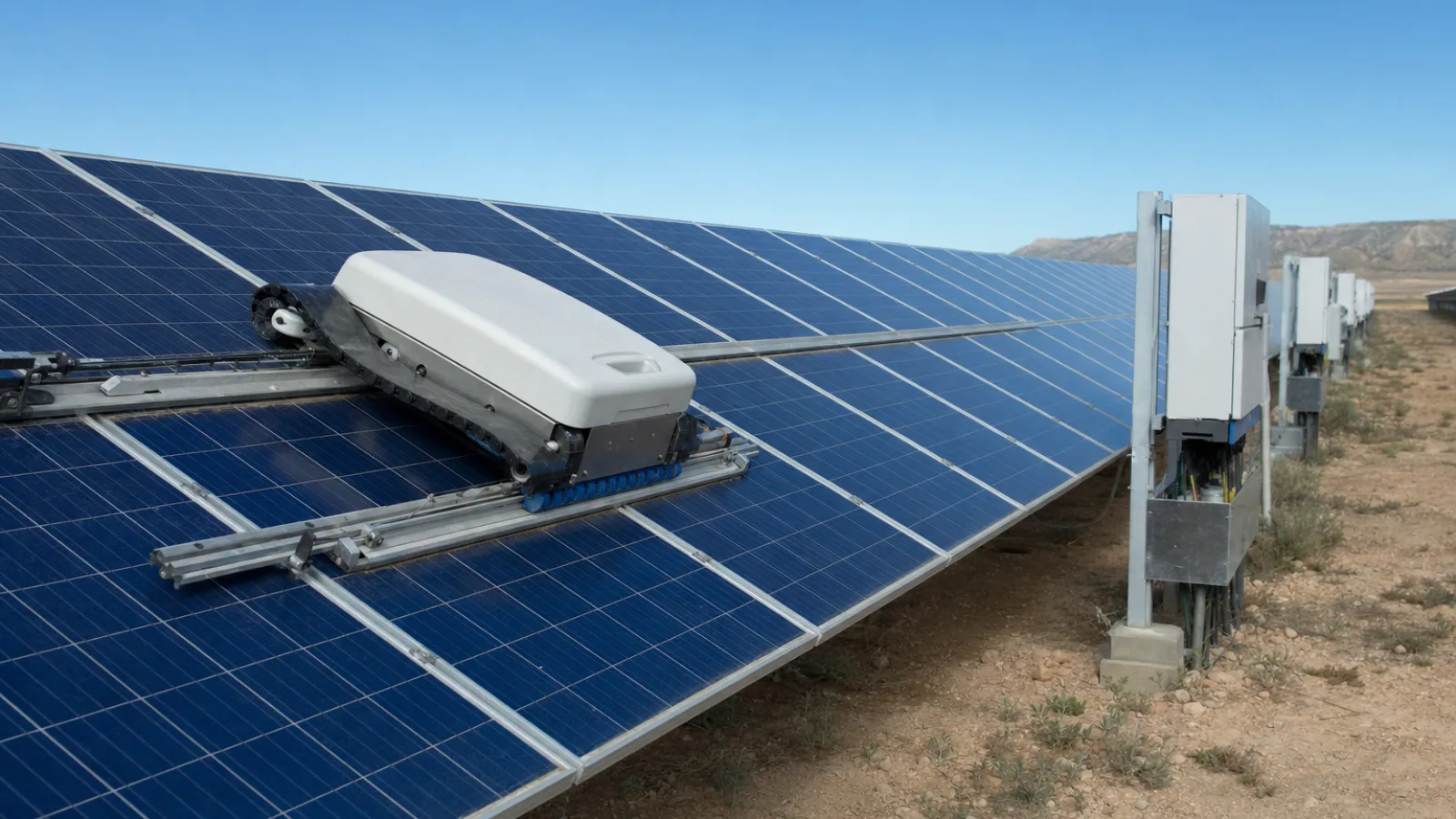
Dust, pollen, salt, bird droppings and windblown debris can accumulate on photovoltaic modules and create uneven operating conditions across an array. In a small rooftop installation, a technician may be able to inspect and clean the modules periodically. On a large ground-mounted plant, however, repeated manual access can become slow, physically demanding and difficult to coordinate with electrical and weather-related risks.
Automated solar panel maintenance addresses this problem by combining mobile cleaning mechanisms, sensors, motor drives, controllers and remote monitoring. The equipment does not simply move a brush across glass. It must travel along a defined path, avoid damaging module surfaces, detect abnormal resistance, manage its power supply and report faults to an operator.
The most suitable system depends on the array geometry, climate, panel framing, row spacing, acceptable water use and maintenance strategy. Automation can reduce routine intervention, but it does not eliminate engineering inspections, electrical testing or decisions by qualified personnel.
Why photovoltaic arrays benefit from automation
Soiling reduces the amount of sunlight reaching the active surface of a module. The effect is not always uniform: a narrow strip of dirt or a bird dropping can shade a smaller area while creating a disproportionate electrical effect in a series-connected string. Accumulated deposits can also make visual inspection more difficult, concealing cracked glass, loose components, corrosion or cable damage.
Large solar sites introduce an operational challenge. Modules may extend across uneven terrain, long rows and restricted-access areas. A maintenance team must coordinate vehicles, fall protection where applicable, electrical isolation and cleaning equipment. Frequent water-based cleaning can also create logistical demands in regions where water is scarce or where mineral deposits could remain on the glass.
Automation is particularly useful when cleaning must be repeated at predictable intervals or triggered by site conditions. A control system can record operating hours, cleaning cycles, motor current and fault events, giving the operator a maintenance history rather than relying solely on visual observations.
What an automated solar maintenance system contains
A typical system is an integrated electromechanical machine rather than a single robot. Its main elements usually include:
- Drive motors and gearboxes: These move the cleaning unit along a rail, module frame or row. Gear reduction provides controlled speed and the torque needed to overcome friction, inclines and brush resistance.
- Actuators: Linear or rotary actuators can adjust brush pressure, deploy stabilising components, open protective covers or position inspection equipment.
- Cleaning tools: Depending on the design, these may include soft rotating brushes, microfiber rollers, air systems, wipers or water-assisted spray and brush assemblies.
- Controllers: A programmable logic controller, industrial embedded computer or dedicated motion controller coordinates movement, sequencing, safety interlocks and fault responses.
- Sensors: Encoders, proximity sensors, limit switches, current sensors, tilt sensors and environmental sensors provide information about position and operating conditions.
- Communications: Wired industrial networks, wireless links or cellular gateways can connect the machine to a local supervisory system or cloud-based monitoring platform.
- Power equipment: Batteries, charging stations, power converters and protected distribution components supply the motors and control electronics.
The mechanical design and control logic must be developed together. A motor with adequate rated power can still create a hazard if the controller cannot detect a jam quickly. Conversely, a sophisticated sensor package cannot compensate for an unstable guide rail or a cleaning head that applies excessive load to the module surface.
How robotic solar panel cleaning works
Most cleaning robots use a constrained route rather than navigating freely like a warehouse vehicle. A carriage may run along the upper or lower edge of a module row, travel on guide rails or use the panel frames as a pathway. The route is established by the array layout, and the robot is designed around the module dimensions, frame heights, gaps and row transitions.
During a cleaning cycle, the controller starts the drive system, confirms that the robot is in its home position and checks selected safety conditions. The machine then moves at a controlled speed while a brush, microfiber element or other tool contacts the surface. At the end of the row, a limit switch, position sensor or encoder count confirms arrival. The robot may return to a docking station, transfer to another row or wait for an operator command.
Dry microfiber systems are useful where water availability is limited and the soil is loose rather than bonded to the glass. A soft microfiber roller can lift fine dust while limiting liquid handling and runoff. The cleaning material must be selected carefully: trapped grit, excessive contact pressure or worn fabric can create abrasion or leave deposits behind.
Water-assisted systems can be more effective against adhered dirt, mud or salt deposits. They may use controlled spray, soft brushes and a recovery or drainage strategy. Water quality matters because dissolved minerals can dry on the module and produce a new layer of residue. The system also needs protection against water entering motors, connectors and control enclosures.
Commercial robotic approaches vary considerably in their mechanical arrangement, navigation method and cleaning process. For a broader example of autonomous solar panel cleaning technology, the relevant engineering questions remain the same: how the machine travels, how it contacts the module, how it is powered and how faults are detected. The presence of an automated robot in an illustration or demonstration should not be taken as evidence that a particular cleaning mechanism or manufacturer is being shown.
Manual cleaning, dry cleaning and water-assisted systems
Manual maintenance remains appropriate for many installations. Technicians can adapt to unusual obstructions, inspect damaged modules closely and use different tools on localised contamination. Its disadvantages are travel time, inconsistent cleaning pressure, worker exposure and the difficulty of maintaining a uniform schedule over a large site.
| Maintenance approach | Strengths | Engineering limitations | Best suited to |
|---|---|---|---|
| Manual cleaning | Flexible, capable of detailed inspection and adaptable to irregular layouts | Labour-intensive; access, safety and consistency must be managed | Small arrays, complex roofs and corrective work |
| Dry microfiber or brush robot | Low or zero routine water use; repeatable travel and scheduling | May be less effective against bonded deposits; brush wear and grit must be controlled | Large arrays in dry regions with loose dust |
| Water-assisted robot | Can address heavier or adhered contamination and support a controlled process | Requires water management, weather protection and attention to mineral residue | Sites where cleaning water and drainage are practical |
| Inspection-focused robot | Can gather repeatable visual, thermal or electrical-condition data | Does not necessarily remove contamination; sensor calibration is important | Condition monitoring and targeted maintenance planning |
This comparison is not a universal ranking. A dry system may be unsuitable after mud or industrial fallout, while a water system may be impractical in a remote desert site. The correct choice follows from the contaminant, module manufacturer’s cleaning recommendations, available infrastructure and required cleaning frequency.
Sensors that keep cleaning robots on track
Position and travel feedback
Proximity sensors can detect a frame edge, docking target or transfer point without physical contact. Limit switches provide a defined end-of-travel signal and can act as a secondary protection layer. Rotary encoders measure motor or wheel rotation, allowing the controller to estimate distance and detect a mismatch between commanded and actual movement.
Encoder feedback is especially useful when wheel slip, changing friction or a partial obstruction makes time-based movement unreliable. If the motor continues to turn but the measured travel does not increase as expected, the controller can stop the machine and issue a fault. The exact detection method depends on the mechanical design and should not be treated as a substitute for physical end stops or independent safety circuits.
Load, contact and environmental sensing
Motor-current monitoring can reveal a jam, excessive brush pressure or a guide problem. Force or contact sensors may be used to regulate the cleaning head so that it follows the surface without imposing unnecessary load. Tilt sensors can identify a dangerous change in orientation, particularly on inclined structures or during a derailment condition.
Rain, wind, temperature and humidity data can influence the cleaning decision. For example, a controller may defer a cycle when wet conditions would make dust smear across the glass or when wind could destabilise a lightweight machine. Environmental sensing supports better scheduling, but site operators still need defined operating limits and a method for overriding automatic commands.
PLC control, embedded intelligence and remote monitoring
A PLC-based system is well suited to installations that require deterministic sequencing, hardwired safety inputs and integration with industrial equipment. The PLC can manage states such as parked, ready, cleaning, returning, charging and faulted. It can also interlock movement with access gates, emergency-stop circuits and docking contacts.
An embedded controller may provide more flexible motion control, data logging, camera processing or wireless communication. In a larger architecture, a local controller handles real-time operation while a supervisory platform records cycle history, alarms and equipment condition. Remote monitoring should expose useful information rather than simply report that a robot is online. Examples include cleaning completion, battery condition, motor temperature, repeated stalls, abnormal current and communication loss.
Fault handling is a central part of the design. A robust sequence should stop or slow the machine when it reaches an unexpected limit, loses position feedback, detects excessive drive load or cannot confirm a safe docking condition. Operators need clear alarm descriptions and a local recovery procedure. Remote reset commands should not defeat physical safety controls.
Structural and mechanical design constraints
Solar modules are designed to carry environmental loads through their frames and mounting systems, not to serve as general-purpose walkways. A robot must therefore be supported in a way that stays within the module and mounting system’s permitted loading conditions. Designers need to examine frame geometry, rail stiffness, fasteners, guide alignment and the effect of repeated rolling or brushing.
Weight distribution is important. A concentrated wheel load can differ significantly from a distributed carriage load, and a machine that bridges two modules can transfer forces into both frames. Vibration from a drive motor or rotating brush may loosen components over time if the structure lacks adequate stiffness or damping. Clearances must also account for frame tolerances, thermal movement, cable loops and debris.
The cleaning interface requires particular care. Hard particles caught beneath a brush can scratch glass or coatings, while excessive pressure can stress a module frame. Brush speed, contact force, travel speed and cleaning-material wear should be treated as controlled design variables. Any system added to an existing plant should be checked against module warranty requirements and the original mounting design.
Electrical safety, weather protection and emergency shutdown
PV modules can produce electrical energy whenever they are illuminated, even when an individual inverter or motor circuit is isolated. Maintenance planning must distinguish the robot’s low-voltage control system from the array’s DC and AC equipment. Access routes, isolation procedures, connectors and enclosures should be evaluated by qualified personnel familiar with the installation.
Outdoor equipment requires suitable protection against rain, dust, ultraviolet exposure, condensation and temperature changes. Cable management is more than an aesthetic issue: loose cables can snag on frames, become abraded or interfere with drainage. Flexible cable carriers, protected routing and strain relief help control those risks.
Emergency-stop devices should remove hazardous motion and place the machine in a defined safe state. Physical stops, guarded pinch points, current limits and independent travel limits provide layers of protection. A robot should also fail safely after a communications outage or power interruption rather than resume motion unexpectedly when the connection returns.
Scheduling, predictive maintenance and lifecycle cost
Cleaning should be based on operating conditions and the value of the energy recovered, not on a fixed calendar alone. Site teams can combine visual inspections, soiling observations, weather information, production trends and historical cleaning results. Automated systems make it easier to run repeatable cycles during low-risk operating windows, but a schedule still needs review after unusual dust events, storms or construction activity nearby.
Predictive maintenance uses operating data to identify deterioration before a failure stops the robot. Rising motor current may indicate bearing wear, guide contamination or brush resistance. Increasing travel-time variation can suggest wheel slip or alignment problems. A growing number of communication interruptions may point to antenna, network or power issues.
Lifecycle cost includes more than the initial robot purchase. Designers should account for installation, guide modifications, charging infrastructure, water supply where relevant, replacement brushes or microfiber materials, software support, inspections, spare parts and technician access. Automation is most defensible when its repeatability and reduced routine intervention outweigh those costs under the site’s actual conditions.
Where automated maintenance reaches its limits
Robots work best on arrays designed or selected for predictable travel. Uneven module heights, broken frames, abrupt row transitions, irregular roof geometry and obstructions can interrupt movement. Cable clips, clamps, fasteners and drainage details may become collision points if they were not considered during system design.
Contamination is another limitation. A dry brush may remove loose dust but struggle with cement residue, oily deposits or hardened bird droppings. A water-assisted process may improve removal but introduce water consumption, runoff and drying concerns. Extreme heat, high winds, freezing conditions, heavy rain and accumulated snow can all require the machine to remain parked.
Automated cleaning also does not replace broader PV maintenance. Technicians still need to examine mounting structures, test electrical equipment, investigate underperforming strings, verify grounding and inspect damage after severe weather. Robotic data is most valuable when it supports those decisions rather than creating the impression that the array is self-maintaining.
The next stage of photovoltaic maintenance automation
Future systems are likely to combine cleaning with more detailed condition monitoring. Cameras, thermal sensors and machine-vision software could help identify soiling patterns, cracked modules, vegetation encroachment or damaged cable routes. The practical value will depend on image quality, calibration, lighting conditions and the ability to distinguish a genuine defect from dirt or glare.
More capable scheduling systems may also coordinate cleaning with production forecasts, weather data, battery charging and site access. Modular robots could be selected for different row types, while digital maintenance records could connect robot faults with work orders and spare-parts planning.
The sound engineering approach is incremental: define the cleaning problem, verify module and structure compatibility, design safe motion and then add monitoring that improves decisions. Automation can make photovoltaic maintenance more consistent and measurable, but its success depends on mechanical fit, environmental suitability and disciplined safety controls as much as on the robot itself.